Introduction to Omron Proximity Sensors
Omron proximity sensors are widely used in industrial automation for detecting the presence or absence of objects without physical contact. These sensors operate based on electromagnetic fields, inductive principles, or capacitive sensing, making them suitable for various applications, including manufacturing, packaging, and assembly lines. Understanding the wiring diagram is crucial for proper installation, ensuring reliable operation and system safety. This guide provides a detailed overview of Omron proximity sensor wiring, covering key components, connection methods, and troubleshooting tips.
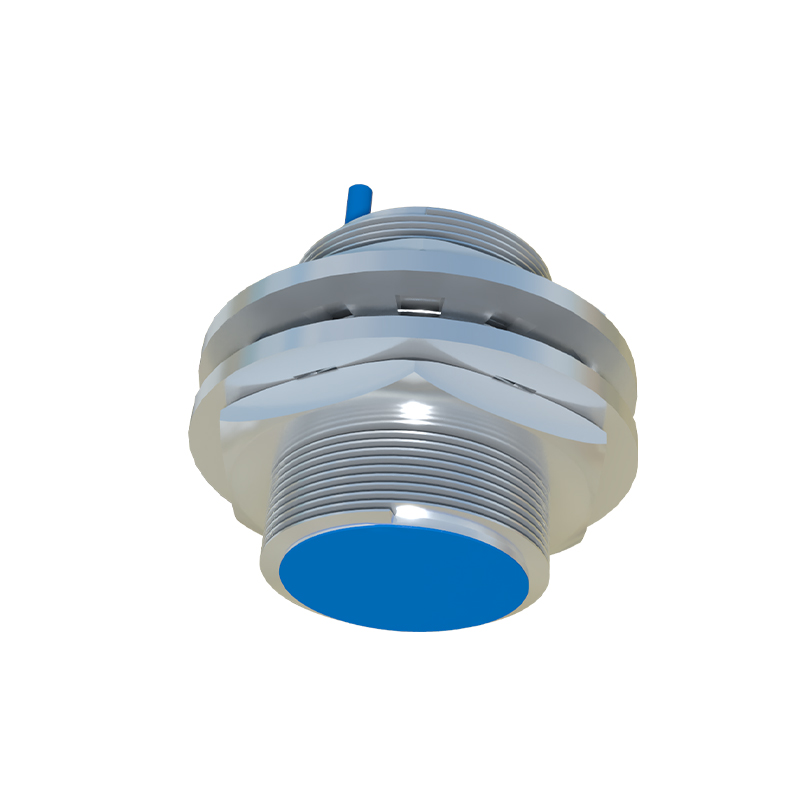
Key Components in the Wiring Diagram
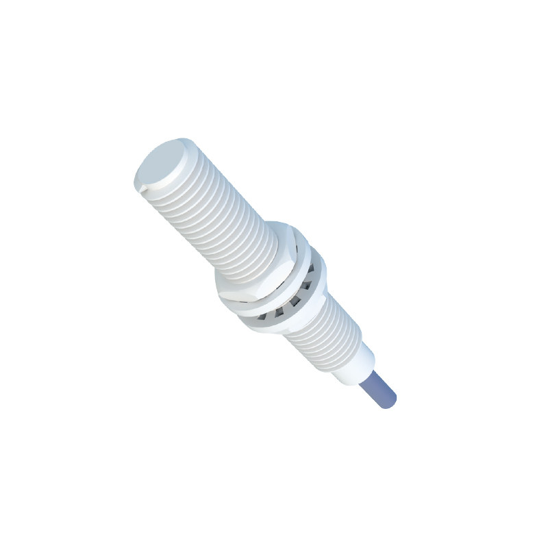
A standard Omron proximity sensor wiring diagram includes several essential components. The sensor itself typically has three or four wires, depending on the model and type (e.g., NPN or PNP output). Common wires are brown for positive voltage supply, blue for negative or ground, black for output signal, and white for auxiliary functions in some versions. The diagram also shows the power source, often a DC supply ranging from 10-30V, and the load device, such as a PLC input module or relay. Additional elements may include protective devices like fuses or surge suppressors to prevent damage from electrical noise or overloads.
Wiring for NPN and PNP Output Types
Omron proximity sensors are available in two main output configurations: NPN and PNP. For NPN sensors, the output wire (black) connects to the load, which is then linked to the positive supply. This setup is known as sinking output, where the sensor switches the ground connection. In contrast, PNP sensors have a sourcing output, with the black wire providing a positive signal to the load connected to ground. The wiring diagram must match the sensor type to the control system; for instance, NPN is common in Asian markets, while PNP is preferred in Europe. Incorrect wiring can lead to malfunction or damage, so always verify the sensor specifications before installation.
Step-by-Step Wiring Procedure
To wire an Omron proximity sensor correctly, start by disconnecting the power supply to avoid electrical hazards. Refer to the sensor's datasheet for the specific wiring diagram, as models like the E2E or TL series may have variations. Connect the brown wire to the positive terminal of the DC power source and the blue wire to the negative terminal. Attach the black output wire to the input point of the load device. If using a shielded cable, ground the shield at one end to reduce electromagnetic interference. After connections, secure the wires with appropriate terminals and inspect for loose contacts. Finally, restore power and test the sensor by bringing a target object within its sensing range.
Common Wiring Mistakes and Solutions
Errors in wiring Omron proximity sensors can cause operational issues. A frequent mistake is reversing the power supply polarity, which may damage the sensor internally. Always double-check the brown and blue wire connections. Another issue is improper grounding, leading to unstable signals or noise interference; ensure the ground point is stable and minimal. Using incorrect wire gauges can also result in voltage drops, affecting sensor performance. Refer to Omron's technical manuals for recommended wire sizes. If the sensor fails to detect objects, verify the wiring against the diagram and check for obstructions or misalignment in the sensing area.
Troubleshooting and Maintenance Tips
Regular maintenance and troubleshooting help prolong the life of Omron proximity sensors. If the sensor does not operate, use a multimeter to measure voltage at the power terminals, ensuring it matches the rated value. Inspect the output signal with an oscilloscope or indicator light to confirm switching action. Clean the sensor face periodically to remove dust or debris that could impair detection. In environments with high vibration, secure the wiring with cable ties to prevent disconnection. For persistent problems, consult Omron's support resources or replace the sensor if it shows signs of wear, such as cracked housing or corroded connectors.
Applications and Best Practices
Omron proximity sensors are versatile, used in applications like object counting, position sensing, and safety systems. For optimal performance, follow best practices such as maintaining the recommended sensing distance, avoiding metal surfaces that could cause false triggers, and using compatible accessories like mounting brackets. When integrating with PLCs, ensure the input module matches the sensor's output type and voltage. Document the wiring setup for future reference, and train personnel on proper handling procedures. By adhering to these guidelines, you can enhance system reliability and reduce downtime in industrial operations.
Conclusion
Understanding the Omron proximity sensor wiring diagram is essential for successful installation and operation in industrial settings. By familiarizing yourself with the components, output types, and wiring steps,