Introduction to Photoelectric Sensor Mounting
The reliability and accuracy of a photoelectric sensor system are fundamentally tied to its physical installation. While the sensor's electronic components receive significant attention, the plastic bracket—the critical interface between the sensor and its environment—is often overlooked. These plastic housings and mounting fixtures, captured in detailed images, reveal a world of engineering considerations aimed at ensuring optimal performance, durability, and ease of integration. From material selection to geometric design, every aspect of the bracket influences the sensor's ability to detect objects consistently in demanding industrial settings. High-resolution images of these components serve as essential references for design engineers, maintenance technicians, and procurement specialists, providing visual confirmation of specifications that datasheets alone cannot fully convey.
Key Features Visible in Bracket Imagery
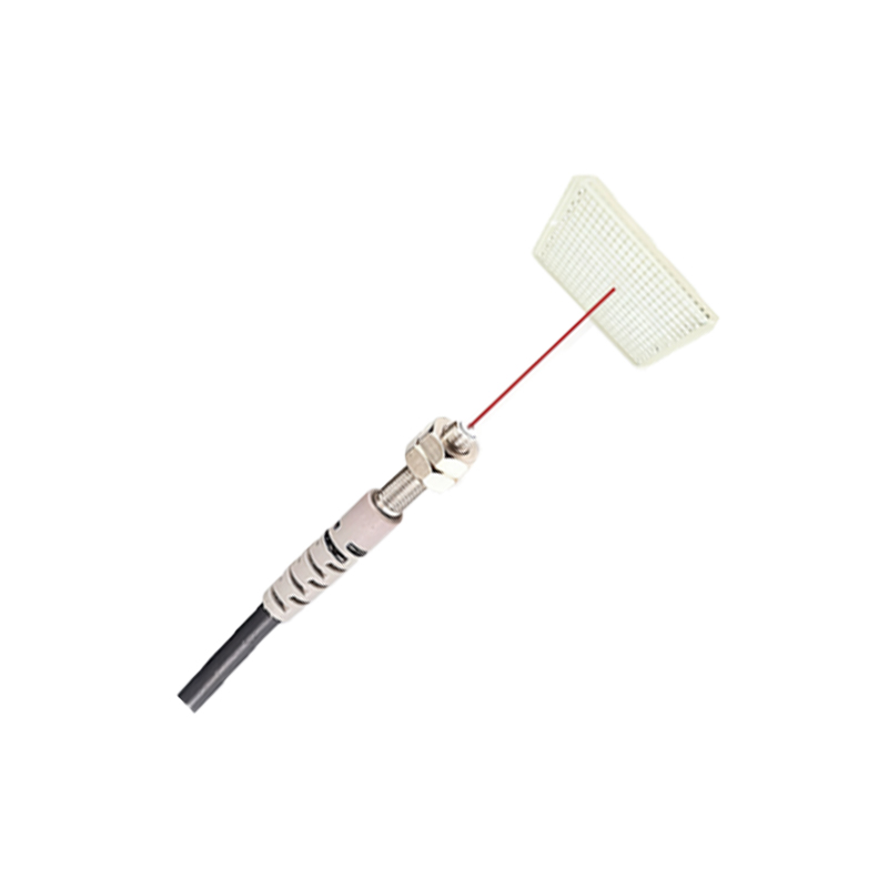
Analyzing professional-grade images of photoelectric sensor plastic brackets allows for the identification of several critical design features. First, the mounting mechanism is clearly visible, whether it features standard threaded holes, quick-release tabs, or slots for adjustable positioning. The imagery often highlights the bracket's articulation points, showing potential for pan, tilt, and rotation to precisely align the sensor beam. Furthermore, details such as cable entry points, strain relief provisions, and sealing gaskets (often indicated by overmolded elastomers) can be assessed. The presence of mounting aids like visual alignment markers or bubble levels integrated into the bracket design is also evident. These visual cues are paramount for understanding the bracket's installation flexibility and its suitability for specific applications like conveyor monitoring, packaging machinery, or automated assembly lines.
Material and Environmental Considerations
Close-up images provide tangible evidence of the polymer used in bracket manufacturing. Engineers can look for visual indicators of material properties. For instance, glass-filled nylon or polycarbonate composites often have a specific texture and rigidity, crucial for vibration resistance and long-term dimensional stability. Images can also reveal the bracket's resistance to environmental factors. Signs of UV stabilization, color consistency (where black pigmentation is common for light interference reduction), and surface finish indicate suitability for harsh conditions. Corrosion resistance is inherent in plastic, but images showing clean, mold-free finishes with no signs of stress whitening assure suitability for washdown environments (IP67/IP69K ratings). The visual confirmation of material integrity helps in preempting failures due to chemical exposure, extreme temperatures, or mechanical impact.
Interpreting Design for Specific Sensor Types
The bracket design is intrinsically linked to the photoelectric sensor type it supports. Through-housing (retro-reflective) sensor brackets, for example, typically feature a large, unobstructed front aperture in images, allowing both emitter and receiver lenses to function. Diffuse sensor brackets might show a more compact, integrated front design. For polarized retro-reflective sensors, brackets may include built-in filter slots or specific lens alignment features. Images of brackets for fiber-optic sensor amplifiers clearly display the delicate ferrule holders and securing clamps. Furthermore, brackets designed for background suppression sensors often have elongated shapes to accommodate the triangulation optics within. Recognizing these design nuances in imagery ensures the correct bracket is selected to maintain the sensor's specified sensing range, beam pattern, and rejection of background objects.
Installation and Maintenance Insights from Visual Guides
Technical images are invaluable installation guides. They demonstrate the practical aspects of mounting, such as the required clearance around the sensor for beam access and cooling. Images showing the bracket from multiple angles—top, side, bottom, and isometric views—clarify spatial requirements and fastener locations. Exploded-view diagrams, sometimes included in image galleries, illustrate the assembly order of brackets, sensors, locking nuts, and protective covers. For maintenance, images can highlight wear points, such as hinge joints or repeated adjustment areas. Visual guides also help identify part numbers molded into the bracket, streamlining the replacement process. This visual documentation reduces installation errors, minimizes downtime, and ensures the sensor system operates at its designed efficiency throughout its lifecycle.
The Role of Imagery in Procurement and System Design
In the specification and procurement phase, detailed images of plastic brackets complement technical datasheets. They enable direct visual comparison between offerings from different manufacturers, assessing factors like build quality, design elegance, and potential for customization. For system designers, 2D and 3D CAD model images (often available for download) are crucial for integration into machine designs, allowing for accurate interference checks and space planning within control panels or on equipment frames. High-quality product photography builds confidence in component quality, while cutaway or cross-sectional images provide insight into internal features like ribbing for added strength. Ultimately, these visual assets bridge the gap between theoretical specifications and physical implementation, ensuring a seamless fit and function in the final automated system.