What Are E2E Proximity Sensors?
E2E proximity sensors, a specific category within the inductive sensor family, are designed for non-contact detection of metallic objects. The term "E2E" is often used interchangeably with "cylinder-style" or "tubular" inductive sensors, referring to their standardized cylindrical metal housing. These sensors operate on the principle of electromagnetic induction. An internal oscillator generates a high-frequency electromagnetic field that radiates from the active face of the sensor. When a metallic target enters this field, eddy currents are induced on the target's surface. This causes a change in the oscillation amplitude within the sensor, which is detected by a threshold circuit, triggering a solid-state output switch. Their robust, threaded metal body makes them exceptionally durable for harsh industrial environments, offering resistance to vibration, moisture, and contaminants.
Key Components Visible in E2E Sensor Images
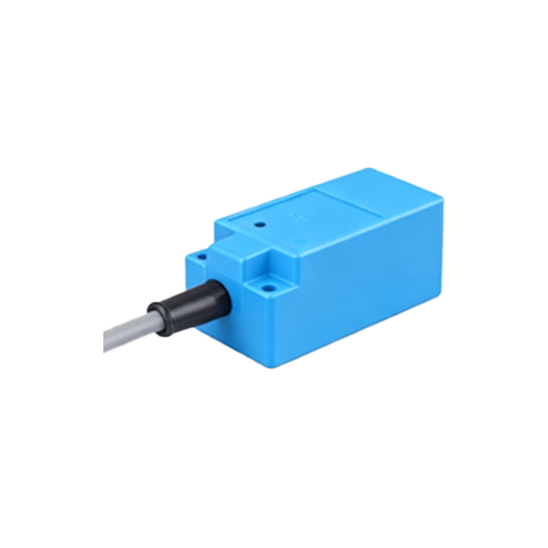
Examining detailed pictures of E2E sensors reveals their critical construction elements. The most prominent feature is the stainless steel or nickel-plated brass threaded barrel, typically ranging from M8 to M30 in diameter. The sensing face, located at one end, is often a flat or slightly recessed disc made of a material that allows the electromagnetic field to pass through, such as PTFE or a specific ceramic compound. Many images will highlight the LED indicator, usually embedded in the rear or side of the housing, which provides visual status feedback for power and output activation. The connection point is also clearly visible, either as a pre-wired cable exiting from the rear or a quick-disconnect plug connector. Some advanced models may show additional features like teach-in buttons or potentiometers for adjusting sensing distance.
Interpreting Sensing Range and Mounting from Diagrams
Technical diagrams and cutaway images are invaluable for understanding the operational characteristics of E2E proximity sensors. A fundamental specification illustrated in these visuals is the nominal sensing distance (Sn), such as 2mm, 5mm, or 8mm. Diagrams often depict this as a clear zone in front of the sensor face. Crucially, images and drawings demonstrate the importance of flush or non-flush mounting. Non-flush (unshielded) sensors have a longer sensing range but require a clear metallic-free area around them for proper operation. Flush (shielded) sensors can be mounted flush in metal without affecting their performance, though their sensing range is slightly reduced. Diagrams typically show the correct and incorrect mounting scenarios, emphasizing the need to maintain the specified lateral and axial clearance for non-flush types.
Output Configuration and Electrical Wiring Schematics
Pictures of sensor nameplates and wiring schematics are essential for electrical integration. E2E sensors are available in three primary DC output types: NPN (sinking), PNP (sourcing), and NO/NC (normally open or normally closed). These are universally denoted by standardized IEC symbols. A clear wiring diagram will show the connection of the brown wire (typically +V), blue wire (0V or common), and black wire (load output), along with the necessary load (like a PLC input or relay). For AC or AC/DC universal models, the wiring differs, usually involving two wires. High-resolution images of the connection area or plug pinout prevent installation errors. Furthermore, many modern E2E sensors feature short-circuit, overload, and reverse polarity protection, which is often indicated by specific markings or icons on the housing.
Application-Specific E2E Sensor Variants in Real-World Photos
Real-world application photos showcase the diversity of E2E sensors tailored for specific challenges. For example, weld-field immune variants are designed with special circuitry and filtering to ignore the electromagnetic interference from nearby welding equipment, a critical feature in automotive manufacturing. All-stainless-steel models, with their fully welded bodies, are depicted in washdown and food & beverage applications where corrosion resistance and hygiene are paramount. High-temperature sensors, capable of withstanding ambient temperatures up to 120°C or more, are shown installed near ovens or foundries. Conversely, extended sensing range versions, sometimes called "factor-1" sensors for non-ferrous metals, are visualized in applications detecting aluminum or copper. These specialized images help engineers select the precise sensor for their environmental and functional requirements.
Analyzing Performance Graphs and Response Characteristics
Beyond physical appearance, technical documentation includes graphical representations of sensor performance. Key graphs often found in datasheets include the hysteresis curve, which plots the switch-on and switch-off points relative to the target distance, illustrating the sensor's repeatability and noise immunity. Another vital graph shows the sensing distance as a function of the target material, comparing steel, stainless steel, aluminum, and copper. Frequency response graphs