Introduction to Photoelectric Sensor Wiring
Photoelectric sensor wiring diagrams are essential blueprints that illustrate the electrical connections required for proper sensor operation. These diagrams depict how the sensor interfaces with power supplies, controllers, and output devices in an automation system. Typically, they include symbols representing the sensor's components, such as the emitter, receiver, and output circuitry, along with terminals for power, ground, and signal wires. Understanding these diagrams is crucial for ensuring correct installation, troubleshooting, and integration into industrial setups. Engineers rely on them to verify voltage requirements, current ratings, and compatibility with programmable logic controllers (PLCs) or other control units.
Key Components in Wiring Diagrams
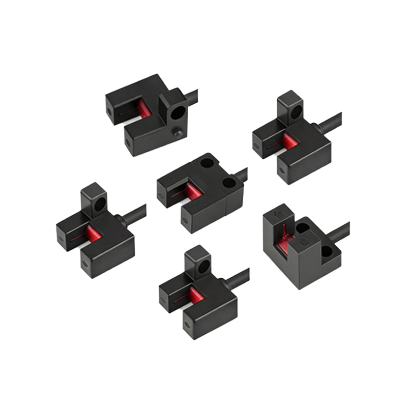
Wiring diagrams for photoelectric sensors highlight several core components. The power supply section specifies voltage levels, often ranging from 10-30 VDC for DC sensors or 90-250 VAC for AC models. Output terminals indicate connections for relay, transistor, or analog outputs, which control external devices like motors or indicators. Additionally, diagrams show wiring for light-on/dark-on operation modes, where the sensor activates based on the presence or absence of detected light. Protective elements, such as short-circuit or reverse-polarity safeguards, may also be included to prevent damage. Labels like "Brown wire for +V," "Blue wire for 0V," and "Black wire for output" are common, following international color-coding standards for consistency.
Interpreting Symbols and Notations
To decode photoelectric sensor wiring diagrams, familiarity with electrical symbols is necessary. Rectangles often represent the sensor housing, while arrows denote light beams between emitter and receiver. Numbers or letters next to terminals correspond to pin assignments, such as "1" for power positive and "2" for output. Notations like "NO" (normally open) or "NC" (normally closed) describe output states under different conditions. Diagrams may also include notes on shielding for noise reduction in high-interference environments. By mastering these symbols, technicians can quickly identify connection points and avoid errors that could lead to malfunction or safety hazards.
Wiring Configurations for Different Sensor Types
Photoelectric sensors come in various types, each with distinct wiring needs. Through-beam sensors, with separate emitter and receiver units, require two sets of wires for power and output, often connected in series with control systems. Retro-reflective sensors use a single device with combined wiring, while diffuse sensors integrate emitter and receiver in one housing, simplifying connections. Diagrams for background suppression sensors include additional terminals for sensitivity adjustments. For example, a 4-wire DC sensor might have two wires for power and two for output, whereas a 3-wire AC sensor could combine common and output lines. Always refer to manufacturer-specific diagrams, as configurations vary by model and application.
Practical Installation Guidelines
When installing photoelectric sensors based on wiring diagrams, start by disconnecting power to prevent electrical shocks. Strip wires to the recommended length and secure them to the correct terminals using screwdrivers or connectors, ensuring tight connections to avoid loose contacts. Route wires away from high-voltage cables or moving parts to minimize interference and physical damage. After wiring, test the sensor with a multimeter to verify voltage and output signals. For complex systems, document connections with labels or tags for future maintenance. Regular inspections, as per diagram guidelines, help detect wear or corrosion in wiring over time.
Troubleshooting Common Wiring Issues
Wiring problems in photoelectric sensors often stem from incorrect interpretations of diagrams. Frequent issues include reversed polarity, where positive and negative wires are swapped, causing sensor failure or damage. Loose connections can lead to intermittent operation, while overvoltage from mismatched power supplies may burn out components. Use wiring diagrams to check for continuity, shorts, or open circuits with testing tools. If the sensor doesn't respond, verify that output loads match the diagram's specifications—overloading can trip protective circuits. Consulting diagrams during troubleshooting saves time and reduces downtime in production lines.
Advanced Applications and Integration
In advanced automation, photoelectric sensor wiring diagrams extend to network integrations, such as IO-Link or Ethernet/IP systems. These diagrams include additional terminals for communication cables, enabling real-time data exchange with PLCs for monitoring parameters like detection range or signal strength. Diagrams for safety-rated sensors highlight redundant wiring paths to meet industry standards like ISO 13849. For smart factories, diagrams may incorporate wireless modules or diagnostic LEDs, with wiring for auxiliary functions. Engineers use these detailed schematics to design scalable, efficient systems that enhance productivity and reliability.
Conclusion and Best Practices
Mastering photoelectric sensor wiring diagrams is key to leveraging their capabilities in industrial settings. Always prioritize safety by following diagram instructions and using personal protective equipment. Keep diagrams updated with any modifications, and train personnel on interpretation techniques. As technology evolves, stay informed about new wiring standards or digital interfaces. By adhering to these practices, you can ensure optimal sensor performance, reduce errors, and maintain smooth operations across applications from packaging to robotics.