Understanding Proximity Sensor Wiring Basics
Before initiating any testing procedures, a fundamental understanding of proximity sensor wiring is paramount. Most industrial proximity switches, whether inductive, capacitive, or photoelectric, typically have a three-wire or four-wire configuration. The three-wire sensors are common, comprising a brown wire for positive supply voltage (typically +24V DC), a blue wire for the negative/common (0V), and a black wire for the switched output signal. Four-wire sensors often include an additional wire, usually white, for a complementary output or a second channel. It is critical to consult the specific sensor's datasheet for the exact pinout and voltage specifications, as colors can vary by manufacturer. Ensuring the correct power supply is connected is the first step to avoid damaging the sensor during testing.
Essential Tools and Safety Precautions
Gather the necessary tools before starting. A digital multimeter (DMM) is indispensable for measuring voltage, continuity, and resistance. Insulated screwdrivers, wire strippers, and a stable DC power supply matching the sensor's rating are also required. Safety is non-negotiable. Always de-energize the circuit before making physical connections or disconnections whenever possible. If live testing is necessary, wear appropriate personal protective equipment (PPE). Verify the multimeter leads are in good condition and set to the correct measurement function. Lock-out/Tag-out (LOTO) procedures should be followed in industrial environments to ensure the system cannot be accidentally re-energized.
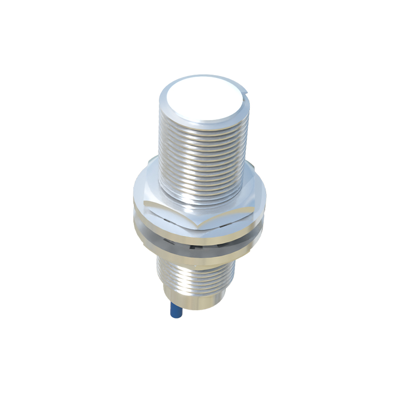
Testing for Power Supply Integrity
The first electrical test is to verify the power supply at the sensor's connection point. With the circuit powered on, carefully set your multimeter to measure DC voltage. Place the black probe on a confirmed ground or the blue wire (common). Touch the red probe to the brown wire (positive supply). The reading should be within the sensor's specified range, usually 24V DC ±10%. A significantly lower voltage indicates a problem upstream, such as a faulty power supply, excessive voltage drop due to long wire runs, or a high-resistance connection. Next, check between the blue wire and the system ground to ensure the common line is at 0V potential, confirming a proper return path.
Continuity and Resistance Checks on Wires
Power down the system completely for these tests. Use the multimeter's continuity or resistance (ohms) function. Disconnect the sensor from the controller. Test each wire individually for opens and shorts. Place one probe on the sensor's terminal end of a wire and the other on the controller connection end. A low resistance (near 0 ohms) and an audible beep indicate good continuity. An infinite reading (OL) means the wire is broken. Next, check for short circuits between wires. Probe between the brown and blue, brown and black, and blue and black wires. All should show a very high resistance (OL) when the sensor is disconnected. A low resistance reading here indicates damaged insulation causing a short.
Measuring the Sensor Output Signal
This test determines if the sensor is functioning correctly. Reconnect power to the sensor. Set the multimeter to DC voltage. With the black probe on the blue (common) wire, touch the red probe to the black (output) wire. Observe the reading when a target is absent and when presented to the sensor's sensing face. For a normally-open (NO) sensor, the voltage should be near 0V (or supply voltage for a PNP type, depending on wiring) without a target and switch to near the full supply voltage (or 0V) when a valid target is detected. The opposite is true for a normally-closed (NC) sensor. A failure to switch states indicates a faulty sensor. Ensure the target material and distance are within specifications.
Diagnosing Common Wiring Faults
Specific symptoms point to common wiring issues. If the sensor has no power, check for blown fuses, tripped circuit breakers, or loose terminal blocks. Intermittent operation often stems from poor crimps, loose connections, or wire strands shorting in a terminal. A sensor that is always "on" might have a short between the output (black) and positive (brown) wires. A sensor that is always "off" could have a short between the output and common (blue) wires or a broken output wire. Environmental factors like moisture ingress can cause corrosion and high-resistance paths, leading to erratic behavior. Visually inspect cables for cuts, abrasions, or pinch points.
Advanced Troubleshooting with an Oscilloscope
For persistent or complex issues