Introduction to Photoelectric Sensors
Photoelectric sensors are pivotal components in modern electrical and automation systems, utilizing light beams to detect the presence, absence, or distance of objects. These devices operate by emitting a light source—typically infrared, visible, or laser—and measuring the reflected or interrupted light to trigger electrical signals. Widely applied in industrial automation, safety systems, and consumer electronics, photoelectric sensors offer non-contact detection, high precision, and reliability. Understanding their graphical symbols is essential for engineers and technicians to interpret circuit diagrams, design control systems, and ensure seamless integration across various applications. The symbols, standardized by international norms, provide a universal language for schematics, enabling clear communication in global engineering projects.
Standardization of Graphical Symbols
Graphical symbols for photoelectric sensors are governed by international standards such as IEC 60617 and ANSI/IEEE 315, which ensure consistency in electrical documentation. These symbols depict the sensor's function rather than its physical appearance, using geometric shapes and lines to represent components like emitters, receivers, and output circuits. For instance, a basic photoelectric sensor symbol often includes a circle or rectangle with inward and outward arrows indicating light transmission and reception, accompanied by labels for power connections and signal outputs. Adherence to these standards minimizes errors in circuit design and facilitates collaboration among engineers from different regions, as symbols convey technical information without language barriers.
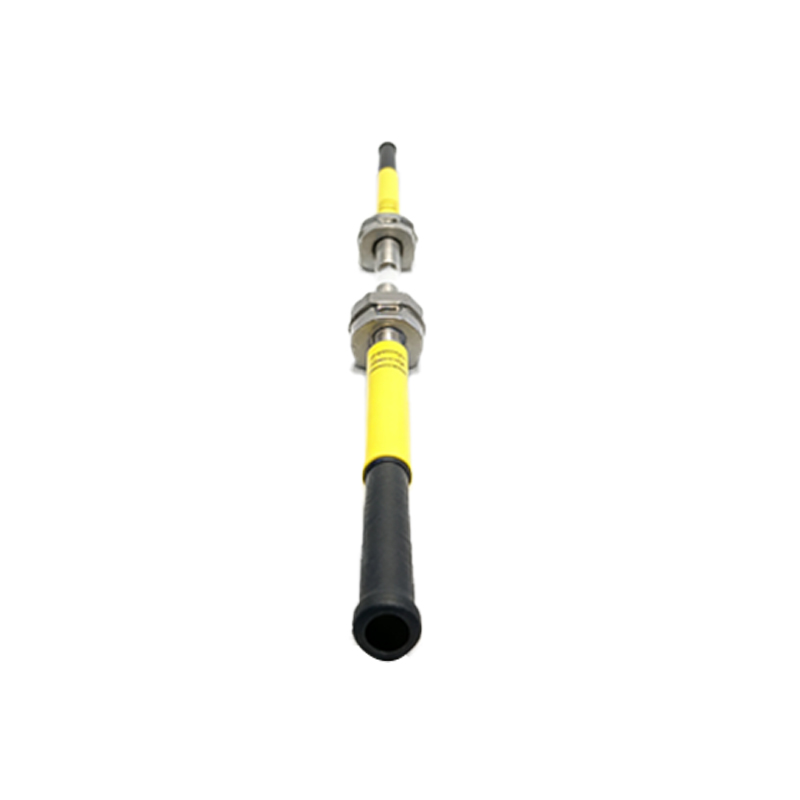
Common Photoelectric Sensor Symbols
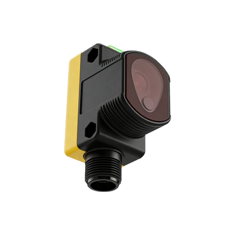
Several key symbols are prevalent in electrical schematics for photoelectric sensors. The through-beam sensor symbol typically shows two separate units: a transmitter (represented by a diode-like shape with an arrow pointing outward) and a receiver (with an arrow pointing inward), connected by dashed lines to signify the light path. Reflective sensor symbols combine both elements into a single symbol, often with a curved line indicating the reflection off a target object. Diffuse sensors use a similar integrated symbol but may include additional markings to denote the scattering of light. Proximity sensors, which detect objects without direct contact, might incorporate a wave-like line to represent the sensing field. Each symbol includes terminals for power supply (e.g., Vcc and GND) and output pins (e.g., NO/NC contacts) to interface with control systems like PLCs.
Interpreting Symbols in Circuit Diagrams
To effectively use photoelectric sensor symbols, engineers must interpret them within the context of circuit diagrams. Symbols are accompanied by alphanumeric codes that specify parameters such as voltage ratings, output types (e.g., PNP or NPN), and sensing ranges. For example, a symbol might include "PS-001" as a reference designator, with notes indicating a 12-24V DC operating range and a normally open output. In ladder logic or wiring diagrams, these symbols connect to other components like relays, timers, or microcontrollers, forming complete control loops. Misinterpretation can lead to wiring errors or system failures, so it's crucial to cross-reference symbols with manufacturer datasheets and standard guidelines. Practical training in reading schematics enhances troubleshooting skills and ensures efficient installation and maintenance.
Applications and Industry Relevance
Photoelectric sensor symbols are integral to diverse industries, from manufacturing and robotics to automotive and aerospace. In conveyor systems, symbols represent sensors that detect product positions, triggering actuators for sorting or packaging. In safety applications, such as light curtains, symbols depict arrays of sensors that halt machinery when obstructed, preventing accidents. The symbols also appear in building automation for occupancy sensing in lighting control, and in consumer devices like printers for paper detection. As Industry 4.0 advances, with trends toward IoT and smart factories, these symbols evolve to include digital interfaces and network indicators, reflecting sensors with embedded connectivity for real-time monitoring and data analytics.
Best Practices for Using Symbols
When incorporating photoelectric sensor symbols into electrical designs, engineers should follow best practices to ensure clarity and accuracy. Always use up-to-date symbol libraries from trusted sources, such as CAD software or standard publications, to avoid outdated representations. Label symbols clearly with unique identifiers and include a legend or bill of materials for easy reference. Consider the sensor's environmental factors—like ambient light or material properties—which might affect performance, and annotate diagrams with installation notes if necessary. Regular reviews of schematics with team members help catch discrepancies early. Additionally, staying informed about updates to standards, such as IEC 61346, ensures compliance with the latest industry practices, fostering innovation and safety in electrical engineering projects.
Conclusion and Future Trends
Mastering photoelectric sensor graphical symbols is a fundamental skill for electrical professionals, enabling precise communication and efficient system design. As technology progresses, symbols may adapt to represent new features like wireless connectivity, energy-efficient designs, or AI-enhanced sensing capabilities. The ongoing harmonization of global standards will further streamline symbol usage across borders. By prioritizing education on these symbols and engaging with industry communities, engineers can drive advancements in automation and contribute to smarter, more responsive electrical systems. Ultimately, a deep understanding of these graphical elements supports the development of robust and innovative solutions in an increasingly automated world.