Introduction to Proximity Sensor Wiring
Proximity sensors are fundamental components in modern industrial automation, providing non-contact detection of objects. Among the various types, three-wire DC sensors are exceptionally common. A standard color coding for these wires is black, blue, and brown. This color scheme is not arbitrary but follows a widely adopted international convention (often based on IEC standards) to ensure consistency, safety, and ease of installation across different manufacturers and regions. Understanding the function of each wire is critical for proper sensor integration, troubleshooting, and system safety. Miswiring can lead to sensor failure, damage to connected controllers like PLCs, or even create safety hazards. This article delves into the specific roles of the black, blue, and brown wires, explaining the underlying electrical principles and their practical implications in circuit design.
The Power Supply Wires: Brown and Blue
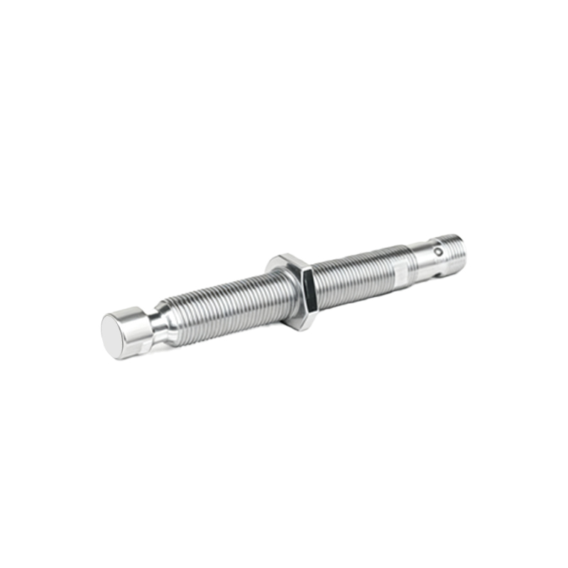
The brown and blue wires are dedicated to providing operating power to the sensor's internal electronic circuitry. In most DC sensor applications following this color code, the brown wire is designated as the positive supply terminal. It should be connected to the positive side of the DC power source. Conversely, the blue wire is universally recognized as the negative supply terminal or common ground. It must be connected to the negative side (0V) of the DC power source. The typical operating voltage range for such sensors is 10-30V DC, but it is imperative to always consult the sensor's datasheet for the exact specifications. Applying power incorrectly, such as reversing brown and blue, will usually prevent the sensor from functioning and may permanently damage its internal components. The consistent use of brown for positive and blue for negative (or neutral in AC contexts) is a key tenet of industrial electrical design that minimizes wiring errors.
The Signal Output Wire: Black
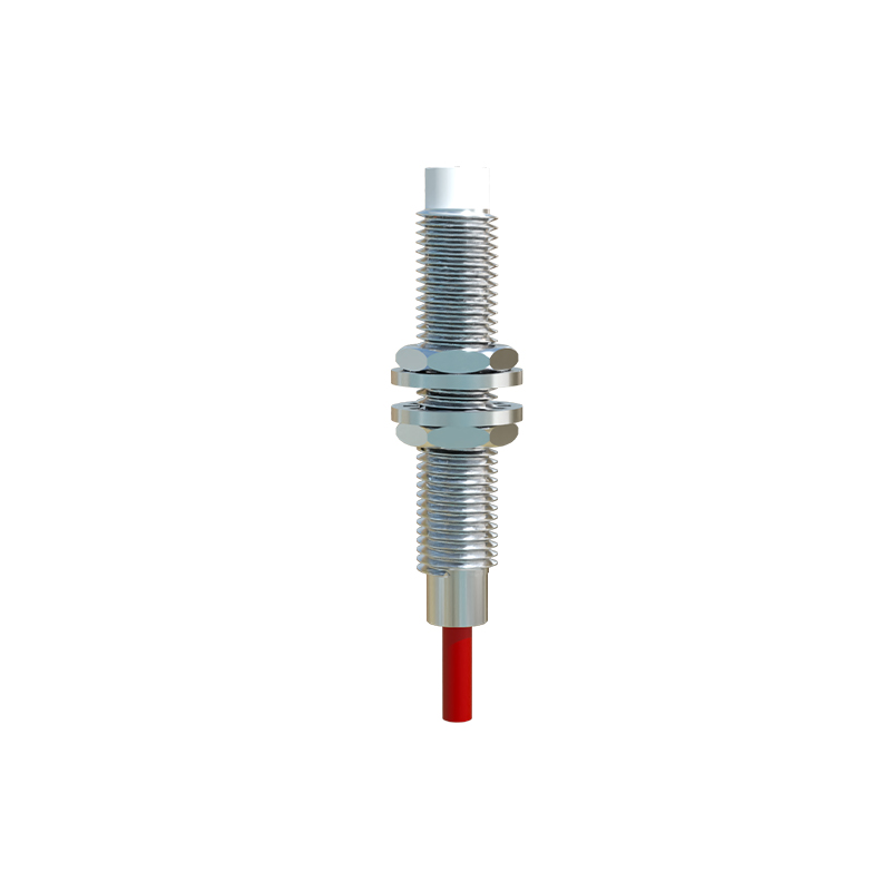
The black wire is the sensor's output signal line. This is the wire that communicates the sensor's detection state to the external control system, typically a Programmable Logic Controller (PLC), relay, or counter. The function of the black wire depends on the sensor's output type. In a sourcing (PNP) sensor, the black wire acts as a positive output. When the sensor detects a target, it internally connects the black wire to the positive supply (brown), sending a positive voltage signal to the load. In a sinking (NPN) sensor, the black wire acts as a negative output. Upon detection, it internally connects the black wire to the negative supply (blue), effectively grounding the signal line to complete the circuit. Choosing between PNP and NPN depends on the input configuration of the controller. It is absolutely crucial to identify the sensor's output type before wiring the black wire to ensure compatibility.
Wiring Diagrams and Circuit Configuration
Visualizing the circuit clarifies the interaction between the wires. For a PNP (sourcing) sensor: The brown wire connects to DC+, the blue wire to DC-. The black wire connects to the input terminal of the PLC. The PLC input itself is connected to DC- internally or externally. When activated, the PNP sensor switches the black wire to DC+, sending current from the sensor to the PLC input. For an NPN (sinking) sensor: The power connections (brown to DC+, blue to DC-) remain identical. However, the black wire now connects to the PLC input, and the PLC input is connected to DC+. When activated, the NPN sensor switches the black wire to DC-, allowing current to flow from the PLC input into the sensor. These configurations highlight why mixing PNP and NPN sensors with incompatible PLC inputs will result in a non-functional system.
Practical Installation and Troubleshooting Tips
Correct installation begins with verifying the sensor specifications on its nameplate. Always de-energize the circuit before making connections. Use ferrule crimps on stranded wires for secure terminations. After wiring, perform a functional test using a target object. Common issues often stem from wiring errors. If a sensor has no power indicator light, check the brown and blue wire connections and voltage levels with a multimeter. If the power light is on but there is no output signal, verify the output type (PNP/NPN) matches the load. A black wire connected to the wrong polarity can cause a short circuit. Additionally, ensure the load (e.g., PLC input) is within the sensor's rated output current capacity. Environmental factors like electrical noise can sometimes induce false signals; using shielded cable and proper grounding of the blue wire can mitigate this.
Industry Applications and Selection Criteria
Three-wire DC proximity sensors with black, blue, and brown wiring are