Understanding the "OUT" Terminal on Photoelectric Sensors
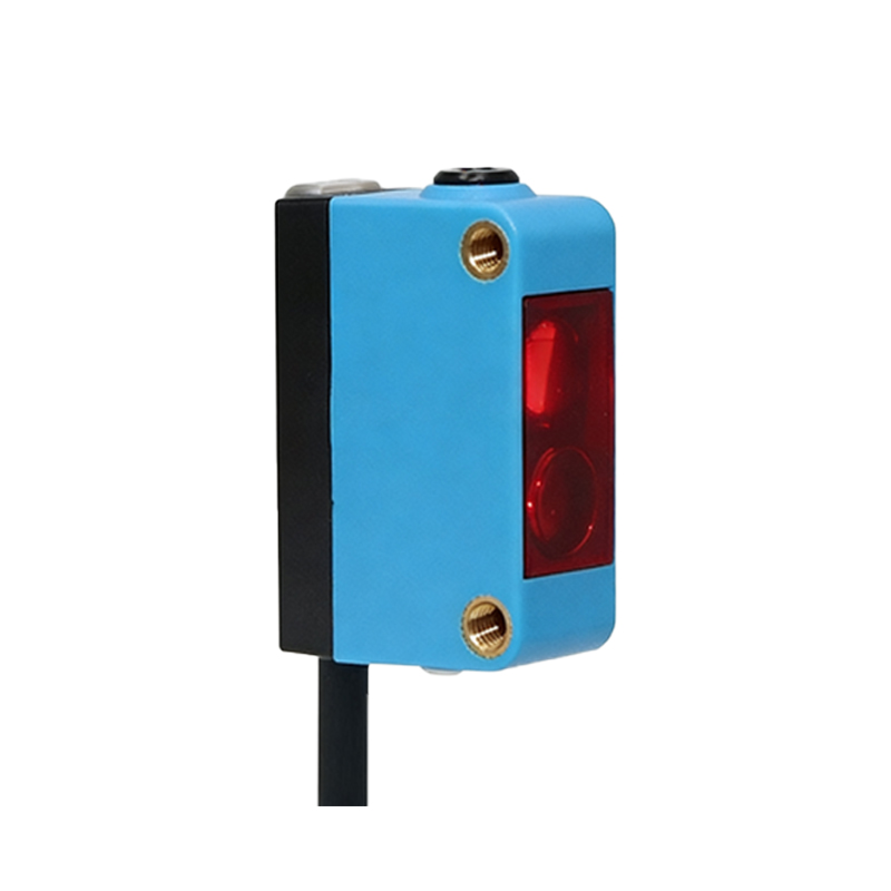
In industrial automation and control systems, photoelectric sensors are ubiquitous devices used for detection, counting, and positioning. A common point of inquiry, especially on wiring diagrams and sensor bodies, is the terminal or connection labeled "OUT." This designation is fundamental to the sensor's operation. Simply put, the "OUT" terminal represents the sensor's output signal line. It is the electrical conduit through which the sensor communicates its detection state to the external world, typically to a Programmable Logic Controller (PLC), a relay, or another control device. The signal present on this line changes based on whether the sensor detects the presence or absence of a target object within its sensing range.
The Nature of the Output Signal: NPN vs. PNP
The electrical behavior of the "OUT" terminal is defined by the sensor's output configuration, which is primarily categorized as either NPN or PNP. This refers to the type of transistor used in the sensor's output switching circuit. For an NPN output sensor (also known as sinking output), the "OUT" terminal acts as a switch to ground (0V). When the sensor is activated (target detected), it connects the "OUT" line to the common ground, allowing current to *sink* into the sensor. Conversely, a PNP output sensor (sourcing output) switches the positive supply voltage. When active, it provides the positive supply voltage (e.g., +24V) *from* the sensor to the "OUT" terminal. Choosing between NPN and PNP is critical and depends on the input characteristics of the receiving control device.
Output Modes: Light-ON and Dark-ON
Closely related to the "OUT" terminal's function is the sensor's operating logic, often selectable via a switch or configuration. This determines the state of the output signal relative to the received light. In "Light-ON" mode (also called Light Operate), the output is activated (turns ON) when the receiver detects the light beam from the emitter. The "OUT" terminal will be in its active state (conducting). In "Dark-ON" mode (Dark Operate), the output activates when the light beam is *blocked*. Understanding this mode is essential for correct system logic. For instance, a transparent bottle on a conveyor might be detected using a retro-reflective sensor in Dark-ON mode, where the output triggers when the bottle interrupts the beam.
Wiring the OUT Terminal in a Practical Circuit
A standard three-wire DC sensor will have connections for Brown (V+), Blue (V- or 0V), and Black (or sometimes White, for OUT). The Black wire is connected to the "OUT" terminal. For a PNP sensor: Brown connects to +24V, Blue to 0V, and the Black (OUT) wire goes to the input channel of the PLC. The PLC input's common would be connected to 0V. When the sensor detects an object, +24V appears on the Black wire, signaling the PLC. For an NPN sensor: Wiring is similar, but the Black (OUT) wire, when active, will connect to 0V. Therefore, the PLC input common must be connected to +24V to complete the circuit. Incorrect wiring can lead to non-operation or potential damage.
Troubleshooting Common OUT Signal Issues
Problems with the sensor's output are often traced back to issues at the "OUT" terminal. If a sensor appears to detect an object (indicator LED may light) but the PLC does not register an input, first verify the voltage at the "OUT" terminal using a multimeter. Check for the expected voltage swing (e.g., from 0V to ~24V for a PNP) when the detection state changes. Ensure the load (PLC input) is within the sensor's rated switching capacity. Also, confirm the operating mode (Light-ON/Dark-ON) is correctly set for the application. Electrical noise, incorrect power supply voltage, or a damaged output transistor can also cause erratic or absent output signals.
Selecting the Correct Output for Your Application
The specification of the "OUT" terminal is a key selection criterion. Beyond NPN/PNP, consider the output type: a solid-state transistor output (standard for PLC connections) or a relay contact output (for switching higher loads or AC voltages). The maximum switching current and voltage (e.g., 100mA, 30V DC) must be respected. In environments with heavy inductive loads (like solenoids), a sensor with a short-circuit protected output is advisable. Always cross-reference the sensor's output characteristics with the input requirements of the receiving device to ensure reliable and safe interfacing within the control panel.