Understanding Proximity Sensor Basics
Proximity sensors are non-contact electronic devices designed to detect the presence or absence of objects within their sensing range. They operate based on various principles such as electromagnetic, capacitive, or inductive technologies. The core function involves generating a signal when a target object enters the detection zone, making them essential in automation, robotics, and safety systems. Proper wiring is critical to ensure accurate detection, reliable operation, and longevity of the sensor. An original wiring diagram serves as the authoritative reference for connecting the sensor to power sources, controllers, and other components, adhering to manufacturer specifications.
Components of an Original Wiring Diagram
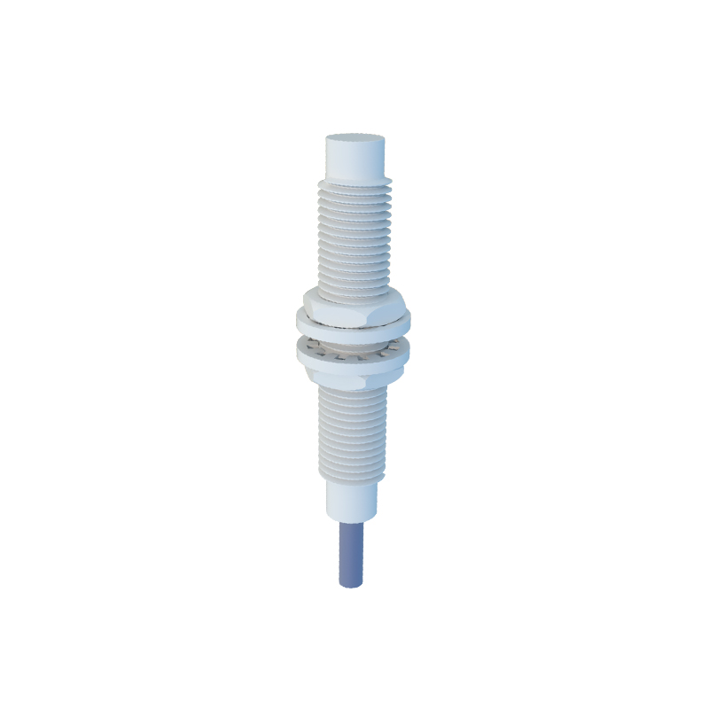
An original wiring diagram typically includes detailed symbols and labels for each terminal, such as power supply connections (e.g., V+ and V-), output signals (e.g., NO/NC contacts), and grounding points. It specifies voltage ratings, current limits, and wire color codes to prevent errors during installation. Diagrams may also indicate shielding requirements for noise reduction in industrial environments. Key elements often featured are the sensor body, cable glands, LED indicators for status, and protection circuits like short-circuit or overload safeguards. Following these components precisely ensures compliance with safety standards and optimal performance.
Step-by-Step Wiring Instructions
Begin by disconnecting all power sources to avoid electrical hazards. Refer to the diagram to identify the sensor's terminals: usually, brown wire for positive DC supply, blue for negative or common, and black for output signal. For AC sensors, terminals may include L (live) and N (neutral). Connect wires according to the specified gauge and insulation type, securing them with appropriate connectors. If the sensor has a relay output, verify the load compatibility with the diagram's ratings. Test connections with a multimeter for continuity before powering on. Always mount the sensor as per diagram guidelines, considering sensing distance and environmental factors like temperature or humidity.
Common Wiring Configurations
Proximity sensors can be wired in different configurations based on application needs. Two-wire models simplify installation by combining power and output in a single loop, but they may have higher leakage current. Three-wire designs separate power and output, offering more stable signals and are common in DC systems. Four-wire versions often include dual outputs or diagnostic features. The original diagram will specify whether the output is normally open (NO) or normally closed (NC), affecting how the control system interprets signals. For complex setups, diagrams might show daisy-chaining multiple sensors or integrating with PLCs using interface modules.
Troubleshooting Wiring Issues
Incorrect wiring is a frequent cause of sensor failure. If the sensor does not activate, check for loose connections, reversed polarity, or voltage mismatches using the diagram as a guide. LED indicators on the sensor can help diagnose issues: a steady light may indicate proper operation, while blinking could signal errors. Ensure wires are not damaged or exposed, and verify grounding to prevent electromagnetic interference. Consult the diagram for fuse ratings or protection devices that might need replacement. In noisy environments, adding ferrite cores or shielded cables as per diagram recommendations can resolve signal instability.
Importance of Using Original Diagrams
Using an original wiring diagram guarantees alignment with the sensor's design and certification standards, such as IEC or UL. It reduces risks of malfunctions, electrical shorts, or voided warranties. Manufacturers update diagrams to reflect product revisions, so accessing the latest version from official sources is crucial. In industrial settings, adherence to these diagrams supports regulatory compliance and enhances system reliability. For custom applications, diagrams provide a baseline for modifications while maintaining safety. Always archive diagrams for future maintenance or troubleshooting reference.
Best Practices for Installation and Maintenance
Regularly inspect wiring integrity based on the diagram's specifications, looking for wear, corrosion, or thermal damage. Use tools like cable testers to verify connections periodically. Label wires according to the diagram to simplify repairs or upgrades. When replacing sensors, compare old and new diagrams to ensure compatibility, as pinouts or ratings may differ. Train personnel on interpreting diagrams to minimize human error. In summary, a proximity sensor's performance hinges on precise wiring, and the original diagram is the definitive tool for achieving this in any electrical engineering project.