Understanding the Yellow Indicator Light
In industrial automation, photoelectric sensors are critical components for detecting the presence, absence, or distance of objects. These sensors typically feature status indicator lights—often green for normal operation and yellow (or amber) for specific conditions. When the yellow light remains constantly illuminated, it signals an operational state that requires attention. Unlike a flashing yellow light, which may indicate a transient issue or warning, a steady yellow glow generally points to a configured mode or a stable abnormal condition. It is essential to consult the specific sensor's manual, as LED color meanings can vary slightly between manufacturers. However, a constant yellow light commonly relates to teaching mode activation, output saturation, or a special function being enabled.
Primary Cause: Teaching Mode or Configuration State
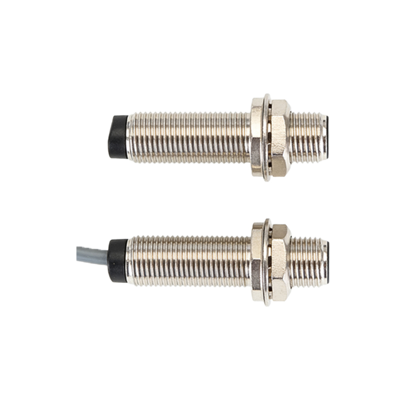
The most frequent reason for a constant yellow light is the sensor being in its "teaching mode" or configuration state. This mode allows users to set or adjust parameters like the sensing distance, sensitivity, or output logic without external programming devices. For instance, in a background suppression sensor, pressing the teach button might trigger a yellow light to indicate it is learning the background distance. The light stays on until the teaching sequence is completed or canceled. Similarly, in sensors with programmable logic or timers, a steady yellow indicator can signify that the device is in a setup menu, awaiting input to configure delay-on or delay-off functions. Always check if any manual buttons have been pressed inadvertently or if the control wiring has triggered this mode remotely.
Output Saturation or Signal Strength Condition
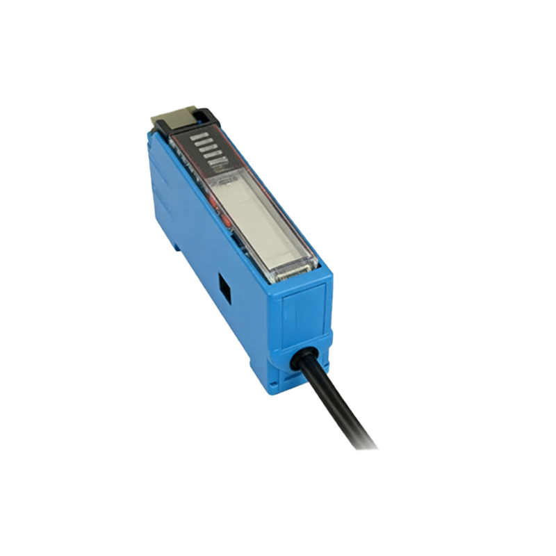
Another common technical scenario is output saturation or a specific signal strength condition. Some photoelectric sensors use a yellow LED to show that the received signal is at or above the threshold required for stable detection, but the sensor might be in a "window" mode where the output is only active within a certain range. If the detected object is too close or too far, causing the signal to be consistently outside the optimal window, the yellow light may stay on to indicate this saturated state. This is particularly relevant in analog or measuring sensors where the yellow light denotes the analog output is at its maximum or minimum limit. Verifying the alignment, sensing distance, and the reflectivity of the target object is crucial in such cases.
Special Function Activation
Modern photoelectric sensors come equipped with advanced functions like diagnostics, maintenance warnings, or communication bus activity indicators. A constant yellow light can be programmed to signify that a special function is active. Examples include a "maintenance warning" that predicts potential failure based on operating hours, an indication of communication via IO-Link or other fieldbus systems without active data exchange, or a "standby" mode in energy-efficient models. In sensors with dual digital outputs, a steady yellow light might indicate that one output is active while the other is in a defined state. Reviewing the function settings via the sensor's interface or software is necessary to identify and reconfigure if needed.
Power Supply and Electrical Issues
While less common, electrical issues can sometimes manifest as a constant yellow indicator. If the sensor operates on a voltage near the lower or upper limit of its specified range, it may enter a protective state indicated by a yellow light. Voltage fluctuations, poor grounding, or electromagnetic interference can also cause the internal circuitry to behave unexpectedly, triggering a fault indication that is not a complete failure (which might be shown by a red light). Ensure the power supply is stable, within the sensor's rated voltage (e.g., 10-30 V DC), and that wiring connections are secure and correct according to the datasheet.
Environmental and Optical Factors
Environmental conditions heavily influence photoelectric sensor performance. Accumulation of dust, dirt, or condensation on the lens can scatter or attenuate the light beam, causing the sensor to operate in a marginal state often indicated by a yellow light. Similarly, intense ambient light from factory lamps or sunlight can saturate the receiver, leading to a constant yellow indicator as the sensor struggles to distinguish its own emitted light. Using sensors with modulated light sources, proper housings (IP67 rated for harsh environments), and installing protective shields or shades can mitigate these issues. Regular cleaning and ensuring the operating environment meets the sensor's specifications are vital maintenance steps.
Troubleshooting and Resolution Steps
To resolve a constant yellow light issue, follow a systematic approach. First, power cycle the sensor by disconnecting and reconnecting the supply to reset any temporary states. Second, consult the product manual for the exact meaning of the LED indicators for your model and series. Third, check the sensor's configuration: if in teaching mode, complete the teaching sequence or exit it as per instructions. Fourth, inspect the application setup—verify alignment, sensing distance, target properties, and for any obstructions. Fifth, measure the power supply voltage and inspect wiring for loose connections or shorts. Finally, if the problem persists, consider restoring factory defaults or contacting technical support, as the sensor may require recalibration or could have an internal fault.
Preventive Measures and Best Practices
Preventing unnecessary yellow light alarms involves proper selection, installation, and configuration. Choose a sensor type (through-beam, retro-reflective, or diffuse) suited to the application's range and environmental challenges. During installation, ensure precise alignment and secure mounting to avoid vibration-induced misalignment. Configure settings like sensitivity, hysteresis, and output mode carefully, documenting the parameters. Implement routine maintenance schedules to clean lenses and check for environmental changes. For complex systems, using sensors with diagnostic capabilities via IO-Link can provide detailed status information directly to the controller, reducing ambiguity and downtime. Training personnel on the specific indicators and functions of the sensors used in your facility is also a key best practice.