Introduction to Industrial Sensing Technologies
In the complex landscape of industrial automation and machinery control, the accurate detection of motion, position, and speed is paramount. Two fundamental components that serve as the eyes and ears of modern control systems are speed sensors and proximity switches. While their primary function—detecting the presence or motion of an object—may seem similar, their operational principles, applications, and output characteristics are distinctly different. This article delves into the technical specifics of both, providing a clear comparison and outlining their critical roles in ensuring efficiency, safety, and precision in automated processes. Understanding the selection criteria for these sensors is essential for any engineer designing or maintaining industrial systems.
Understanding Speed Sensors: Principles and Types
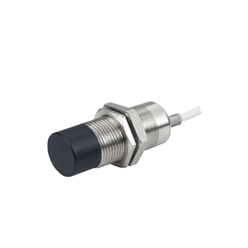
Speed sensors, as the name implies, are specifically designed to measure the rotational or linear speed of a target. Their output is typically a signal whose frequency is directly proportional to the speed of the object being monitored. The most common types are magnetic (inductive) and optical encoders. Magnetic speed sensors, often called variable reluctance sensors, generate an AC voltage signal when a ferromagnetic target, such as a gear tooth, passes through their magnetic field. The frequency of this AC signal directly correlates to the rotational speed. Optical encoders, on the other hand, use a light source and a photodetector interrupted by a coded disk to generate precise digital pulses. Hall-effect sensors are another prevalent type, providing a digital square-wave output in response to a changing magnetic field, making them highly reliable and resistant to environmental contaminants like oil and dust.
Core Functionality of Proximity Switches
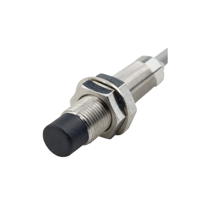
Proximity switches, in contrast, are primarily presence detectors. Their function is to indicate whether an object is within a certain predefined range without any physical contact. They output a simple on/off signal. The most widespread technologies are inductive, capacitive, and ultrasonic. Inductive proximity switches detect metallic objects by generating an electromagnetic field; when a metal target enters this field, it causes a change in oscillation amplitude, triggering the switch. Capacitive sensors can detect both metallic and non-metallic materials (like plastics, wood, or liquids) by sensing changes in capacitance. Ultrasonic sensors use sound waves to measure the time-of-flight to an object, providing both presence detection and distance measurement capabilities. Their output is typically a switched DC signal for a control system's input module.
Key Application Areas and Selection Criteria
The application dictates the choice between a speed sensor and a proximity switch. Speed sensors are indispensable in applications requiring monitoring or control of velocity. This includes motor speed feedback for variable frequency drives (VFDs), conveyor belt speed monitoring, rotational speed measurement in turbines and engines, and overspeed/underspeed protection systems. Proximity switches find their use in position sensing, such as detecting the end of travel on a linear actuator, counting objects on a production line, verifying the open/closed status of a door or valve, and ensuring proper part positioning before a machining operation. Key selection parameters include sensing distance, target material, required output type (analog frequency vs. digital switch), environmental conditions (temperature, humidity, IP rating), and response time.
Installation Considerations and Maintenance
Proper installation is critical for reliable operation. For speed sensors, especially magnetic types, the air gap between the sensor tip and the target (e.g., gear tooth) must be precisely set according to the manufacturer's specifications. Misalignment can lead to weak or erratic signals. Shielding may be necessary in electrically noisy environments to prevent signal interference. Proximity switches require careful consideration of their mounting, ensuring that only the intended target enters the sensing field. Factors like flush or non-flush mounting style for inductive sensors significantly affect the nominal sensing distance. Regular maintenance involves checking for physical damage, buildup of debris on the sensing face (particularly for optical and capacitive types), and verifying the stability of mounting hardware. Electrical connections should be inspected for corrosion or looseness.
Integration with Control Systems and Future Trends
Both sensor types seamlessly integrate into Programmable Logic Controller (PLC) and Distributed Control System (DCS) architectures. The pulsed output of a speed sensor is often connected to a high-speed counter input module, while the discrete signal from a proximity switch connects to a standard digital input. Modern advancements include the development of IO-Link enabled sensors, which provide not only the primary switching signal but also detailed diagnostic data (e.g., operating temperature, signal strength, and device health) over a standard 3-wire connection. This facilitates predictive maintenance and reduces downtime. Furthermore, the miniaturization of components and the increasing robustness of designs are allowing these sensors to operate in more extreme environments, pushing the boundaries of industrial automation.