Understanding Proximity Sensor Fundamentals
Proximity sensors are non-contact devices designed to detect the presence or absence of an object within a specified sensing range. Unlike mechanical limit switches, they operate without physical contact, making them ideal for applications requiring high reliability, fast response times, and minimal wear. The core principle involves generating an electromagnetic field or beam of radiation. When a target object enters this field, it causes a change in the sensor's state, which is then converted into an electrical signal. Common types include inductive sensors for detecting metals, capacitive sensors for detecting both metallic and non-metallic materials, and photoelectric sensors using light beams. Understanding the fundamental operating principle of the specific sensor type—whether it's based on eddy currents, capacitance change, or light interruption—is the critical first step before any installation or wiring begins.
Selecting the Right Sensor for Your Application
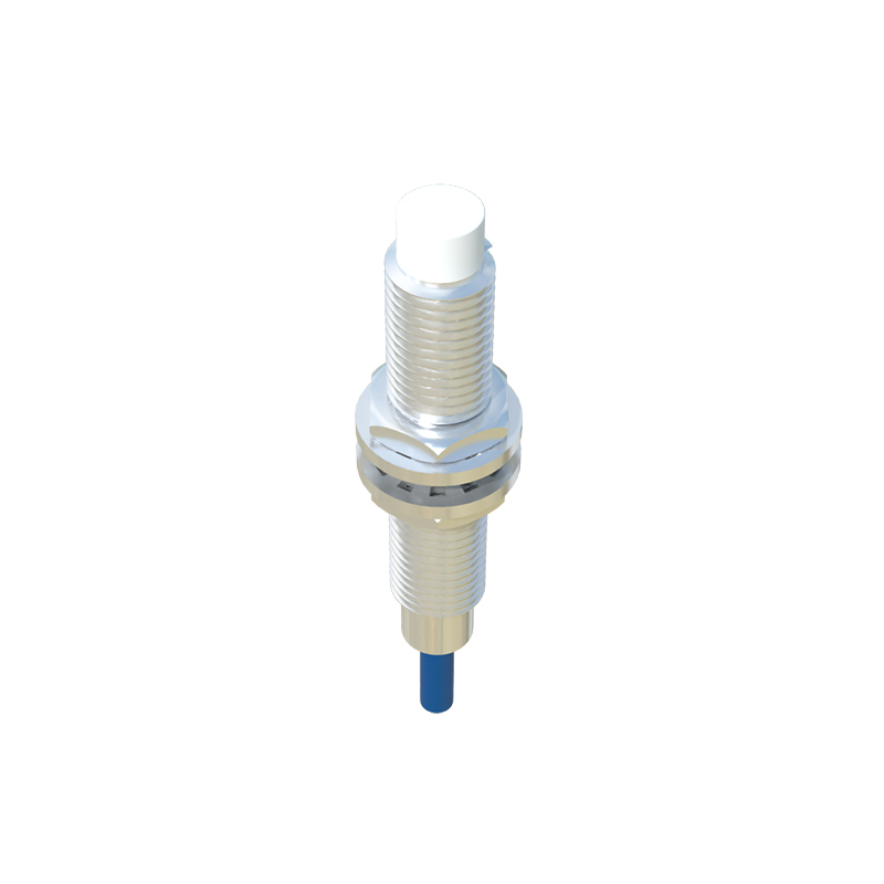
Correct sensor selection is paramount for system performance. Begin by defining the target material. For ferrous and non-ferrous metals, an inductive proximity sensor is typically the most robust and cost-effective choice. For materials like plastic, wood, glass, or liquids, a capacitive sensor is required. Consider the required sensing distance, often referred to as the "rated operating distance" (Sn). Always account for a safety margin; do not operate the sensor at its absolute maximum limit. Environmental factors are crucial: will the sensor be exposed to dust, coolant, extreme temperatures, or strong electromagnetic interference? For harsh environments, look for sensors with high IP (Ingress Protection) ratings, such as IP67 or IP69K. Finally, determine the required output type: a simple 2-wire AC/DC, a 3-wire DC (PNP or NPN sinking/sourcing), or a 4-wire dual-output model. The output must be compatible with your controller's input module (e.g., PLC).
Proper Installation and Mounting Guidelines
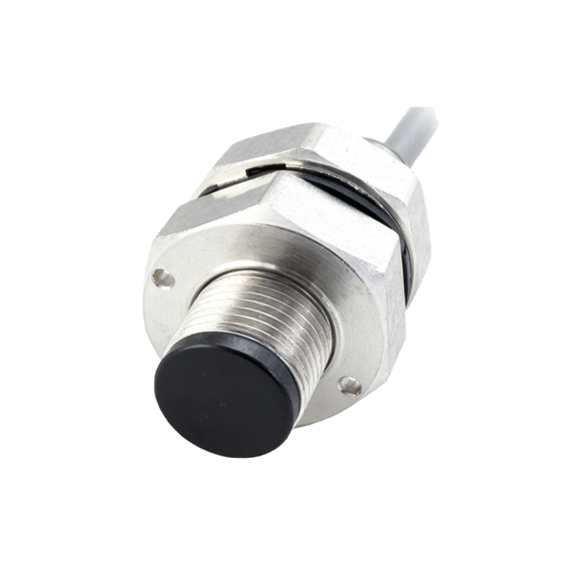
Installation errors are a leading cause of sensor failure. First, ensure the mounting location allows the target to approach the sensor's sensing face correctly. For inductive and capacitive sensors, maintain the specified flush-mount or non-flush-mount clearance. Flush-mountable sensors can be embedded in metal without affecting their range, while non-flush types require free space around the sensing face. Use the correct mounting hardware and torque to avoid damaging the housing. For threaded barrel sensors, use a lock nut to prevent loosening from vibration. Pay close attention to sensor-to-sensor spacing. Installing two identical inductive sensors too close together can cause mutual interference, leading to erratic switching. Refer to the datasheet for the minimum recommended separation distance, which is often twice the sensor diameter. Always orient the sensor so that the sensing face is perpendicular to the expected path of the target for maximum reliability.
Electrical Wiring and Connection Procedures
Incorrect wiring can damage the sensor or the connected controller. Always disconnect power before making any connections. For 3-wire DC sensors, identify the wire colors: typically brown for V+ (positive supply), blue for V- (0V/common), and black for the output signal. A PNP sensor switches the positive voltage to the load; its black wire connects to the PLC input, and the PLC common connects to 0V. An NPN sensor switches the 0V line; its black wire connects to the PLC input, and the PLC common connects to +V. This distinction is critical. Ensure the supply voltage matches the sensor's rated voltage (e.g., 10-30V DC). Incorporate protective devices such as fuses or surge suppressors if the wiring runs long distances or in electrically noisy environments. For 2-wire AC/DC sensors, they are wired in series with the load. Verify the residual current (leakage current) when in the "OFF" state is low enough not to accidentally trigger your PLC input.
Configuration, Testing, and Alignment
After installation and wiring, power on the system for configuration and testing. Many modern sensors feature a built-in LED indicator that shows power status and output activation. Use this LED for initial diagnostics. For adjustable sensors, such as some capacitive models or photoelectric sensors with potentiometers, introduce the target object and adjust the sensitivity threshold. Turn the potentiometer until the indicator LED just activates with the target in place, then add a small safety margin. For photoelectric sensors, precise optical alignment is essential. Use the indicator LED or an alignment tool provided by the manufacturer to ensure the receiver is correctly receiving the beam from the transmitter. Test the sensor by repeatedly introducing and removing the target under normal operating speed conditions. Use a multimeter or an oscilloscope to verify the output signal's integrity, checking for clean switching