Introduction to Proximity Sensing Technology
Proximity sensors are fundamental components in modern industrial automation and electrical control systems. These non-contact devices detect the presence or absence of an object within their sensing field without any physical contact. This capability makes them exceptionally reliable, durable, and suitable for harsh environments where mechanical wear, contamination, or repeated impact would degrade traditional limit switches. The core principle involves generating an electromagnetic or electrostatic field and monitoring changes within that field caused by a target object. Their applications span from simple object detection on conveyor belts to complex positioning tasks in robotics and safety interlocking in machinery guards. The elimination of moving parts translates to virtually infinite operational life, minimal maintenance, and high-speed switching capabilities, which are critical for modern high-throughput manufacturing processes.
Core Operating Principles: Inductive vs. Capacitive
The two primary types of proximity switches relevant to electrical engineering are inductive and capacitive sensors. Inductive proximity sensors are the most common in industrial settings. They generate an oscillating electromagnetic field using a coiled ferrite core. When a metallic object, typically ferrous or non-ferrous metal, enters this field, it induces eddy currents on the object's surface. These currents absorb energy from the oscillator, causing its amplitude to decrease. This damping effect is detected by the sensor's circuitry, which then triggers a solid-state output switch. Their detection range is limited and specifically tuned for metals, making them immune to non-metallic substances like wood, plastic, or liquids.
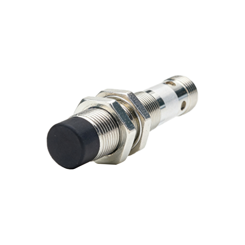
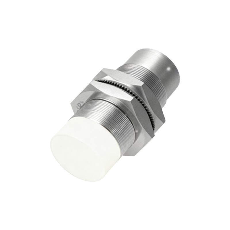
Capacitive proximity sensors, in contrast, can detect both metallic and non-metallic materials. They operate by generating an electrostatic field between two electrodes (often the sensor face and a ground plane). Any object that enters this field alters the dielectric constant and thus the capacitance of the system. The sensor's internal circuit monitors this change in capacitance. Once it exceeds a preset threshold, the output state changes. This makes capacitive sensors ideal for detecting materials like glass, plastics, powders, granules, and liquids through non-metallic container walls. However, they can be more susceptible to environmental factors like humidity or contamination on the sensor face.
Key Electrical Specifications and Selection Criteria
Selecting the correct proximity sensor requires careful analysis of electrical and environmental parameters. The operating voltage is paramount, with common DC versions being 10-30V DC and AC versions ranging from 20-250V AC. The output configuration is equally critical: PNP (sourcing) or NPN (sinking) for DC sensors, and normally open (NO) or normally closed (NC) contacts. The load current rating, typically up to 200mA for standard models, must not be exceeded. The sensing distance, or "sn," is a nominal value defined for a standard target; real-world sensing distance can vary based on target material, size, and shape.
Environmental ratings are non-negotiable for reliability. Ingress Protection (IP) codes like IP67 (dust-tight and protected against temporary immersion) are standard for washdown environments. Temperature ranges, resistance to chemicals, and resistance to electromagnetic interference (EMI) must align with the application. For inductive sensors, the target material composition (steel, aluminum, brass) directly affects the actual sensing range, often requiring derating. For capacitive sensors, the sensitivity adjustment potentiometer allows tuning to ignore certain background materials or container walls.
Wiring, Installation, and Practical Considerations
Proper installation is crucial for optimal performance and avoiding nuisance tripping. For inductive sensors, a metallic mounting surface can reduce the effective sensing range; non-metallic brackets or maintaining a minimum clearance around the sensing face is recommended. Sensors should be mounted securely to prevent vibration-induced false signals. Wiring must follow the manufacturer's diagram precisely, ensuring correct polarity for DC models and proper connection of the brown (L+), blue (L-), and black (output) wires. Shielding and conduit are advised in areas with high EMI from motors or frequency drives.
A critical practice is to ensure the sensor is not wired in a way that allows leakage current to falsely energize a PLC input. Using a bleeder resistor across the input may be necessary. For capacitive sensors, avoiding false triggers from accumulated dust or moisture may require periodic cleaning or selecting a model with a built-in compensation electrode. The sensing face should be kept free of paint, labels, or thick buildup. Always verify switching function with the actual target material under real operating conditions during commissioning.
Advanced Features and Industry Applications
Modern proximity sensors incorporate advanced features that enhance system intelligence. Analog output versions provide a continuous signal proportional to the distance to the target, useful for positioning or thickness measurement. IO-Link enabled sensors offer digital communication for parameter setting, condition monitoring, and diagnostic data (like