Understanding Through-Beam Photoelectric Sensors
Through-beam photoelectric sensors, often called opposed-mode sensors, are a cornerstone of industrial automation. They consist of two separate units: a transmitter and a receiver. The transmitter emits a constant beam of light, typically infrared or laser, which is then detected by the receiver. The core operating principle is simple yet powerful: an object is detected when it physically interrupts this light beam. This mode offers the longest sensing range and highest reliability among photoelectric sensors, as it is less susceptible to surface color, reflectivity, or environmental factors like dust, compared to diffuse-reflective models. In robotic applications, this makes them ideal for precise object detection, part presence verification, and safety guarding at entry/exit points of a work cell. Their high-speed response is critical for synchronizing robotic movements with production line flow.
Essential Components and Pre-Wiring Considerations
Before initiating the wiring process, ensure you have all necessary components. This includes the through-beam sensor pair (transmitter and receiver), appropriate cabling, a suitable power supply (commonly 12-24V DC for industrial sensors), and the robotic arm's controller or a programmable logic controller (PLC) with available digital input points. Carefully review the sensor's datasheet for its specific voltage, current, and output type specifications. Most industrial through-beam sensors provide a digital switched output, either as PNP (sourcing) or NPN (sinking). The choice must be compatible with the input circuit of your robotic controller. Additionally, consider the mechanical mounting. The transmitter and receiver must be securely and precisely aligned on opposite sides of the detection point. Use mounting brackets to ensure vibration resistance and maintain perfect optical alignment, which is crucial for consistent operation.
Wiring the Power Supply to the Sensor Pair
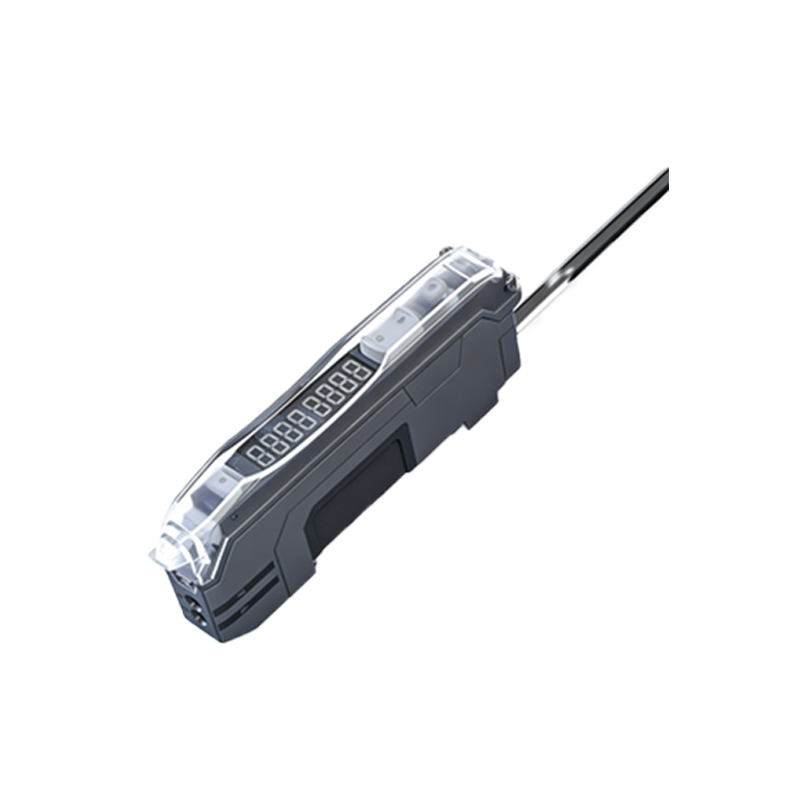
The first electrical step is providing power to both units of the sensor. Typically, the transmitter and receiver have separate but identical power connections. Identify the V+ (or +V, brown wire) and V- (or 0V, blue wire) terminals on each unit. Connect the positive lead from your DC power supply to the V+ terminal on both the transmitter and the receiver. Similarly, connect the negative lead from the power supply to the V- terminal on both units. It is a standard and safe practice to use a fused power supply circuit. This parallel power connection ensures both units are energized from the same source, providing a common reference point and preventing potential ground loop issues. Always follow the color-coding or labeling specified in the sensor's manual, as conventions can vary slightly by manufacturer.
Connecting the Sensor Output to the Robotic Controller
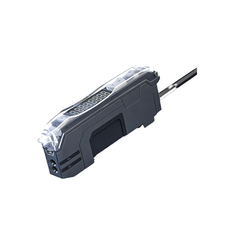
The receiver unit houses the output circuit that signals the detection state. Locate its output terminal, often labeled OUT, NO (normally open), or with a black wire. In a standard wiring configuration for object detection, you will connect this output signal to a digital input (DI) point on your robotic arm's controller or an intervening PLC. For a PNP-type sensor: the output acts as a switching positive voltage. Connect the sensor's output wire to your controller's DI point. Then, connect the common negative (0V) of the sensor's power supply to the common terminal of the controller's input group. When the beam is unbroken, the output is off. When an object breaks the beam, the PNP switch closes, sending the V+ voltage to the controller's input, signaling a "high" or "true" state. For an NPN-type sensor, the output switches the ground path, and the wiring logic is reversed.
Integrating the Signal with Robotic Logic and Safety
Once the physical wiring is complete, integration into the robotic program is essential. Within the robot's teaching pendant or programming software, configure the specific digital input you used to monitor the sensor's state. This input can then be used as a condition in the robot's logic. For example, a common routine is to command the robot to pause its approach or gripping sequence until the sensor confirms a part is present (beam broken). Conversely, the robot may be programmed to only initiate a "place" operation when the sensor beam is clear (unbroken), indicating the drop-off area is vacant. For safety interlocks, such as guarding a hazardous zone, the sensor signal should be hard-wired or programmed into a safety-rated input that can trigger an immediate protective stop (STO) on the robot, independent of the main program cycle.
Testing, Troubleshooting, and Best Practices
After wiring and programming, conduct thorough testing. Power on the system and verify the sensor's alignment indicator (usually an LED) shows a stable "beam received" state. Manually interrupt the beam and confirm the receiver's output LED toggles and the corresponding input status changes in the robot controller. Common issues include misalignment, insufficient power, incorrect wiring of PNP/NPN type, or electrical noise. For long cable runs, use shielded cables and ground the shield at one end to the chassis to prevent interference. Always implement mechanical protection for cables near the robotic arm to prevent wear and tear from continuous movement. Regularly clean the sensor lenses to maintain optical performance and schedule periodic functional checks to ensure the detection system remains reliable within the automated work cell.