Introduction to Photoelectric Sensors
Photoelectric sensors are widely used in industrial automation, robotics, and safety systems due to their non-contact detection capability. These sensors operate by emitting a light beam, typically from an LED or laser diode, and detecting changes in the received light intensity caused by the presence or absence of an object. The core principle involves converting light signals into electrical signals, which are then processed to determine object detection. Common types include through-beam, retro-reflective, and diffuse reflective sensors, each suited for specific applications based on range, environmental conditions, and target properties. Understanding the underlying electronics is crucial for designing reliable sensor circuits, and simulation tools like Proteus can help validate designs before physical implementation.
Basic Components of a Photoelectric Sensor Circuit
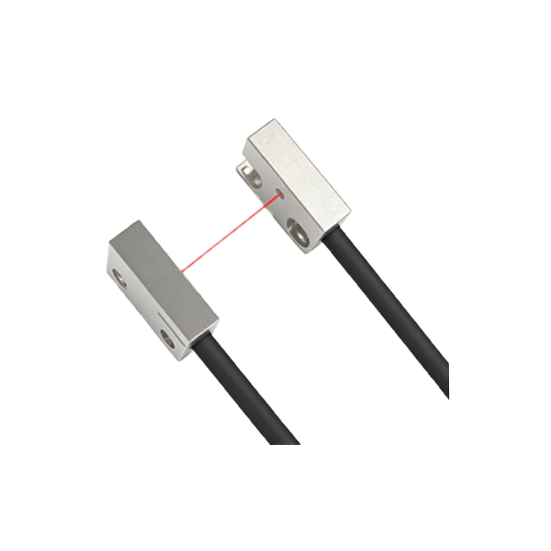
A typical photoelectric sensor circuit consists of several key components. The transmitter section includes a light source, such as an infrared LED, driven by a current-limiting resistor and often modulated with a pulse signal to reduce ambient light interference. The receiver section features a photodetector, like a phototransistor or photodiode, which converts incoming light into a small current. This signal is then amplified using an operational amplifier (op-amp) circuit to a usable voltage level. Additional components may include filters to remove noise, comparators to set detection thresholds, and output stages such as transistors or relays for interfacing with other devices. Proper selection of components ensures sensitivity, response time, and stability in various operating conditions.
Designing the Circuit Schematic in Proteus
Proteus software provides a comprehensive environment for designing and simulating electronic circuits. To create a photoelectric sensor schematic, start by selecting components from the library, including an IR LED, phototransistor, resistors, capacitors, and op-amps like the LM358. Connect the IR LED in series with a resistor to a pulse generator source to simulate modulated emission. Place the phototransistor in a common-emitter configuration, with its collector connected to a pull-up resistor and its emitter to ground. The output from the phototransistor feeds into an op-amp-based non-inverting amplifier stage to boost the signal. Use voltage dividers and potentiometers to set reference voltages for comparators, enabling adjustable detection thresholds. Ensure proper power supply connections and grounding to avoid simulation errors.
Simulation and Analysis in Proteus
Once the schematic is complete, run simulations to analyze circuit performance. In Proteus, use virtual instruments like oscilloscopes and voltmeters to monitor signals. For example, observe the pulsed output from the IR LED and the corresponding signal at the phototransistor output when an object is simulated by blocking the light path. Adjust component values, such as resistor ratios in the amplifier, to optimize gain and sensitivity. Test under different conditions by varying ambient light levels or object distances, which can be modeled by changing light intensity parameters in the photodetector properties. Simulation helps identify issues like insufficient amplification, noise interference, or slow response times, allowing for iterative improvements before building a physical prototype.
Practical Considerations for Real-World Applications
While simulations provide valuable insights, real-world applications require additional considerations. Environmental factors like dust, moisture, or temperature variations can affect sensor performance, so protective enclosures and filtering circuits may be necessary. Power supply stability is critical to prevent false triggers; incorporate voltage regulators and decoupling capacitors in the design. For long-range detection, use focused lenses or higher-power light sources, but ensure compliance with safety standards to avoid eye damage. Output interfacing should match the connected system, whether it's a microcontroller input, PLC, or industrial relay. Testing with actual targets and conditions is essential to validate the design, and Proteus simulations can reduce development time by catching fundamental errors early.
Conclusion and Further Resources
Designing photoelectric sensor circuits in Proteus offers a practical approach to understanding and optimizing detection systems. By leveraging simulation tools, engineers can experiment with different configurations, component values, and environmental scenarios without the cost and effort of physical prototyping. This process enhances reliability and efficiency in industrial applications. For further learning, explore Proteus tutorials on advanced features like PCB layout integration or scripting for automated testing. Additionally, refer to datasheets for specific components and industry guidelines on sensor installation and maintenance. Continuous innovation in photoelectric technology, such as smart sensors with embedded processing, promises even greater capabilities for automation in the future.