Introduction to Proximity Sensor Switches
A proximity sensor switch is a fundamental component in modern industrial automation, designed to detect the presence or absence of an object without physical contact. These switches operate on various principles, including inductive, capacitive, ultrasonic, and optical methods. The core function revolves around generating an electrical signal when a target object enters a predefined sensing range. This non-contact detection offers significant advantages, such as eliminating mechanical wear, enabling high-speed operation, and functioning reliably in harsh environments contaminated with oil, dust, or moisture. Understanding the underlying circuit diagram is crucial for engineers to properly select, integrate, and troubleshoot these sensors within complex control systems. The circuit not only dictates the sensing performance but also defines the output type, whether it is a simple two-wire alternating current (AC) switch, a three-wire direct current (DC) transistor output, or a more sophisticated analog or IO-Link interface.
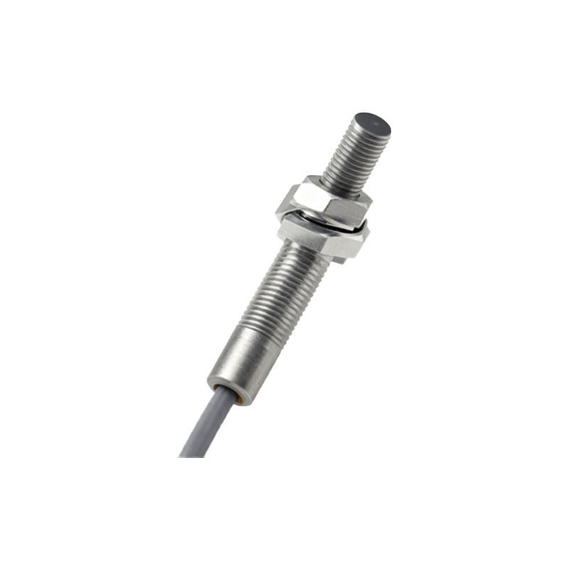
Core Components of the Circuit
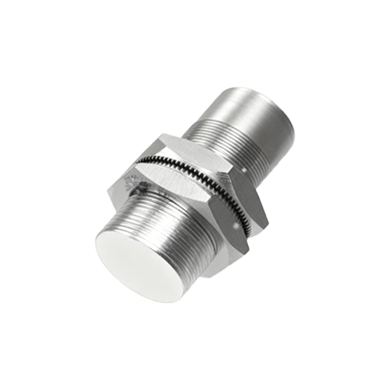
The typical circuit diagram for a standard DC three-wire inductive proximity sensor, one of the most common types, consists of several key sections. The oscillator circuit forms the heart, generating a high-frequency electromagnetic field from the sensor's face. This usually involves a coil (the sensing element), capacitors, and an integrated circuit (IC) to sustain oscillation. When a metallic target enters this field, eddy currents are induced, causing a dampening or change in the oscillator's amplitude. This change is detected by the threshold detection circuit, another critical block within the IC. Following detection, the signal is conditioned and fed into the output driver stage. For a PNP (sourcing) output sensor, this stage typically uses a transistor to switch the positive voltage line to the load. Conversely, an NPN (sinking) output switches the ground connection. The circuit also includes essential protection components like reverse polarity protection diodes, surge suppression devices, and short-circuit protection to ensure durability and safety in industrial settings.
Analyzing a Standard PNP NO Circuit Diagram
Examining a specific diagram for a three-wire, PNP, normally open (NO) DC sensor clarifies the signal flow. The positive supply voltage (V+, often 10-30V DC) connects to the brown wire. The blue wire is connected to the common ground (0V). The black wire is the signal output. Internally, the V+ line powers the oscillator and detection IC. In the absence of a target, the output transistor is in an "off" state, and the black wire is effectively disconnected from V+. Therefore, no voltage is present at the output signal line relative to ground. When a target is detected, the IC switches the output transistor "on." This creates a low-resistance path between the V+ supply (brown wire) and the output (black wire). The black wire now sources current to the load (e.g., a PLC input, relay coil), which is connected between the black wire and ground (blue wire). A free-wheeling diode is often placed across the load to suppress voltage spikes from inductive loads. The simplicity of this switching action makes it highly reliable for digital control tasks.
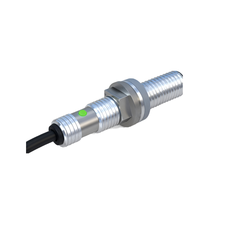
Wiring Configurations and Considerations
Correct wiring is paramount for system functionality and safety. The two-wire AC sensor circuit is simpler, wired in series with the load directly into an AC line (e.g., 120VAC), but it has inherent leakage current. The three-wire DC configuration, as detailed, offers superior performance with virtually zero leakage when off. A critical consideration is the sensor's output type (PNP vs. NPN) relative to the PLC or controller input. PNP sensors are commonly used with sinking PLC inputs, while NPN sensors pair with sourcing inputs. Misconfiguration can lead to non-operation. Furthermore, the circuit diagram dictates the need for a stable, clean power supply. Voltage fluctuations or electrical noise can cause false triggering. Engineers must also adhere to guidelines for cable length, shielding, and separation from high-power cables to prevent electromagnetic interference (EMI) from disrupting the sensitive oscillator circuit, as illustrated by recommended practices in the sensor's datasheet.
Integration with Control Systems
The output from the proximity sensor's internal circuit is rarely the final endpoint. Integration into a broader control system, such as a Programmable Logic Controller (PLC) or a microcontroller, is the ultimate goal. The sensor acts as a binary input device to the PLC. In a standard setup, the sensor's output wire connects to a discrete input module on the PLC. The PLC's internal program then uses this digital status (TRUE/FALSE, 1/0) to make logic decisions—starting a motor, counting parts, or initiating a robotic sequence. For analog output sensors,