Introduction to Photoelectric Sensor Wiring
Photoelectric sensors are essential components in industrial automation, enabling non-contact detection of objects through light-based technology. These sensors operate by emitting a light beam—typically infrared, visible red, or laser—and detecting changes in the received light intensity caused by the presence or absence of an object. The reliability and accuracy of photoelectric sensors make them indispensable in manufacturing, packaging, material handling, and safety systems. A critical aspect of their installation and performance is proper electrical wiring, particularly for models utilizing a 4-wire configuration. This setup is common in DC-powered sensors that require separate connections for power supply and output signals, offering enhanced functionality and flexibility compared to simpler 2-wire or 3-wire designs. Understanding the 4-wire connection method is vital for engineers and technicians to ensure optimal sensor operation, minimize downtime, and maintain system integrity in demanding industrial environments.
Components of a 4-Wire Photoelectric Sensor
A standard 4-wire photoelectric sensor comprises several key terminals, each serving a distinct electrical purpose. The wiring typically includes two wires for power supply and two for output signals. First, the power supply wires consist of a positive voltage input (often labeled V+ or brown wire) and a negative or ground input (labeled V- or blue wire). These connections provide the necessary DC power, commonly 12-24V DC, for the sensor's internal circuitry and light emitter. Second, the output wires include a normally open (NO) or normally closed (NC) signal wire (usually black or white) and a common return wire (often labeled COM or blue). The output configuration allows the sensor to switch a load, such as a relay, PLC input, or indicator, based on detection states. Some sensors may feature complementary outputs (e.g., both NO and NC) or analog outputs, but the 4-wire setup fundamentally separates power and control circuits. This separation enhances electrical isolation, reduces interference, and enables versatile integration with various control systems.
Step-by-Step Wiring Procedure
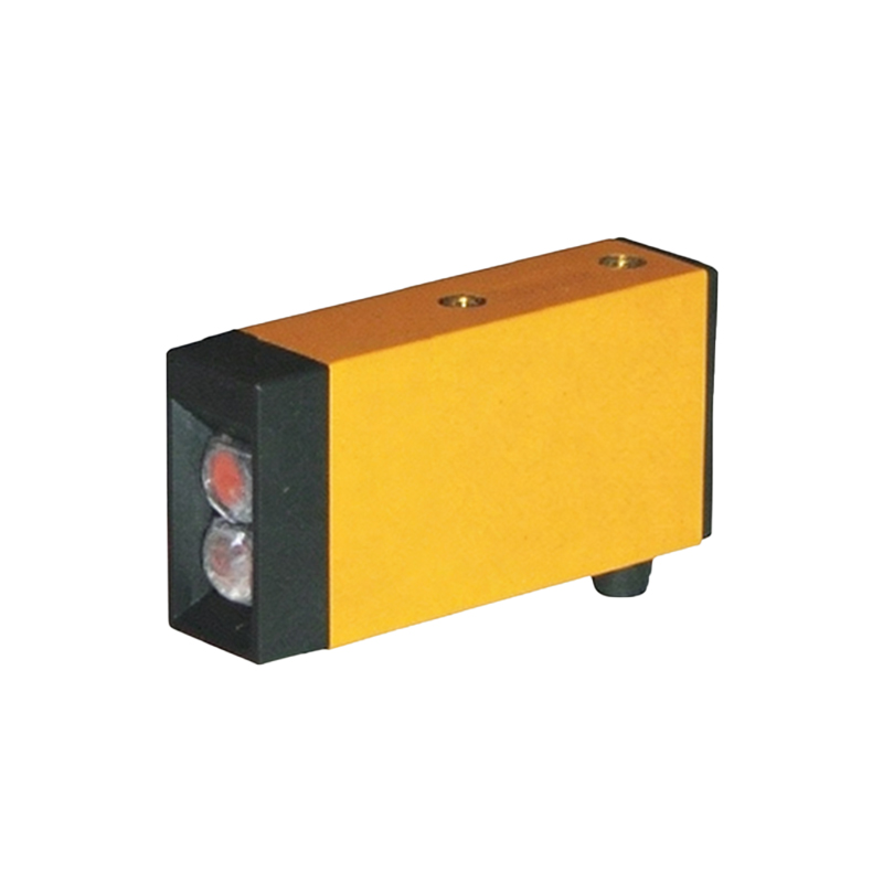
To wire a 4-wire photoelectric sensor correctly, follow a systematic approach to ensure safety and functionality. Begin by de-energizing the control circuit and verifying the sensor's specifications, including voltage rating, output type, and wire color codes, as per the manufacturer's datasheet. First, connect the power supply wires: attach the positive DC supply line to the V+ terminal (brown wire) and the negative supply to the V- terminal (blue wire). Use appropriate wire gauges and secure connections to prevent voltage drops or shorts. Next, wire the output circuit: link the sensor's COM terminal (blue wire) to the common ground of the load circuit. Then, connect the output signal wire (e.g., black for NO) to the input device, such as a PLC digital input module or relay coil. Ensure the load's voltage and current ratings match the sensor's output capacity, typically up to 100-200mA. After wiring, double-check all connections for correctness and insulation. Finally, apply power and test the sensor by observing its indicator LED and output response when an object interrupts the light beam. Proper wiring minimizes false triggers and extends sensor lifespan.
Common Wiring Configurations and Applications
The 4-wire photoelectric sensor supports multiple wiring configurations tailored to specific industrial applications. In a standard switching setup, the NO output closes upon detection, activating a PLC input to trigger processes like conveyor stoppage or part counting. Conversely, the NC output can be used for fail-safe applications, such as safety curtains, where a broken beam signals a fault. For bidirectional control, sensors with dual outputs (e.g., light-on/dark-on modes) allow flexible logic programming. In high-noise environments, shielded cables are recommended for output wires to prevent electromagnetic interference from affecting signal integrity. Additionally, 4-wire sensors often interface with programmable logic controllers (PLCs), motor drives, or human-machine interfaces (HMIs) in automated assembly lines, robotic cells, and packaging machinery. Their ability to handle separate power and signal paths makes them ideal for complex systems requiring precise timing, such as bottling plants or electronic component manufacturing. Always refer to application notes for industry-specific guidelines, like IP ratings for washdown areas in food processing.
Troubleshooting and Best Practices
Effective troubleshooting of 4-wire photoelectric sensor connections involves methodical checks to diagnose common issues. If the sensor fails to operate, first verify power supply voltage with a multimeter at the V+ and V- terminals, ensuring it meets the rated range (e.g., 10-30V DC). Next, inspect output signals: monitor the output terminal voltage relative to COM during detection; a change indicates proper switching. Persistent problems may stem from incorrect wiring polarity, loose connections, or environmental factors like dirt on the lens, ambient light interference, or misalignment. Utilize the sensor's built-in indicators—power LED and output status LED—for quick diagnostics. For optimal performance, adhere to best practices: use twisted-pair or shielded cables for long runs exceeding 10 meters to reduce noise, maintain proper sensing distance within specified limits, and avoid mechanical stress on cables. Regular maintenance, including lens cleaning and periodic electrical tests, ensures reliability. Implementing these practices reduces downtime and enhances system efficiency in industrial settings.
Advantages of 4-Wire Over Other Wiring Methods
Compared to 2-wire or 3-wire sensors, the 4-wire photoelectric sensor offers distinct advantages that justify its use in advanced industrial applications. The separation of power and output circuits in 4-wire designs provides superior electrical isolation, minimizing leakage current and preventing false triggering in sensitive control systems. This isolation also allows for flexible output configurations, such as independent switching of multiple loads or compatibility with both sinking and sourcing PLC inputs. Additionally, 4-wire sensors typically support higher output currents, enabling direct control of relays or small actuators without additional amplifiers. They also feature more stable operation over wide voltage ranges and better resistance to electrical noise, crucial in environments with variable frequency drives or heavy machinery. While 2-wire sensors are simpler for basic on/off tasks, and 3-wire sensors offer a balance of simplicity and performance, the 4-wire variant excels in complex automation scenarios requiring precision, reliability, and integration versatility. Engineers often choose 4-wire sensors for critical processes where downtime is costly, leveraging their robust design for long-term operational integrity.