Understanding Diffuse Reflection in Photoelectric Sensors
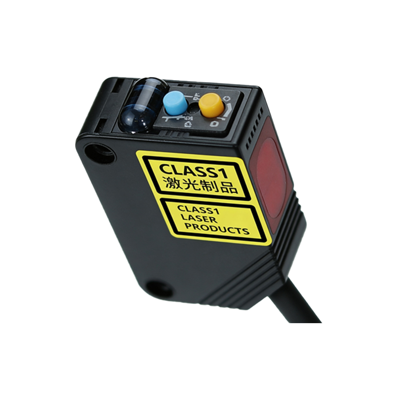
Photoelectric sensors utilizing the diffuse reflection principle are fundamental components in industrial automation. Unlike through-beam or retro-reflective sensors, diffuse reflection sensors house both the light emitter (typically an LED) and the receiver within a single housing. The sensor detects an object when the emitted light beam strikes the target and a sufficient amount of the diffusely reflected light is scattered back to the receiver. This operating principle makes them ideal for applications where mounting a separate reflector or receiver is impractical. Their effectiveness hinges on the reflectivity of the target material, its color, surface texture, and distance. The simplicity of installation, requiring only one wiring point, has cemented their role in countless detection tasks, from object presence on conveyors to part positioning in assembly machines.
Defining the Hysteresis Phenomenon
Hysteresis, in the context of photoelectric diffuse reflection sensors, refers to the intentional and engineered difference between the switch-on point and the switch-off point. It is not a defect but a critical feature designed to ensure stable switching and prevent output chattering or oscillation when an object is positioned near the detection threshold. The switch-on point (or operating point) is the distance at which the sensor detects a target and changes its output state. The switch-off point (or release point) is the distance at which the target moves away and the sensor returns to its original state. The region between these two points is the hysteresis zone. This built-in differential provides a buffer, ensuring that minor fluctuations in object position, ambient light, or sensor temperature do not cause erratic, rapid switching of the output signal.
Primary Causes of Hysteresis and Variation
Several factors influence the magnitude and behavior of hysteresis in a diffuse reflection sensor. The primary cause is the internal electronic circuitry designed to create a stable switching threshold. However, external conditions can alter its effective range. The reflectivity of the target is paramount; a highly reflective white surface will trigger the sensor at a greater distance than a matte black surface, effectively shifting both the on and off points. Changes in ambient temperature can affect the output intensity of the LED and the sensitivity of the receiver, potentially widening or narrowing the hysteresis window. Contamination on the sensor lens, such as dust or oil, attenuates the light beam, reducing the effective sensing range and impacting hysteresis. Finally, power supply voltage variations can also subtly shift the switching characteristics.
Negative Impacts of Excessive or Uncontrolled Hysteresis
While hysteresis is necessary, excessive or unpredictable hysteresis can lead to significant operational issues. The most direct impact is a loss of positional accuracy. If the hysteresis zone is too wide, an object might be detected later than expected or the sensor might continue to detect it even after it has moved further away than the intended tolerance allows. This can cause timing errors in sequential processes. In applications requiring precise edge detection or exact positioning, such as in cutting or dispensing, this inaccuracy can result in product defects. Furthermore, if hysteresis behavior changes unpredictably due to environmental factors like heavy dust or temperature swings, it introduces instability into the control system, leading to inconsistent machine performance and increased downtime for troubleshooting.
Strategies for Minimizing and Compensating for Hysteresis Effects
Engineers can employ several strategies to manage hysteresis and ensure reliable sensor operation. First, meticulous sensor selection is crucial. Choose a sensor with a hysteresis specification suitable for the application's precision needs. Many modern sensors offer adjustable sensitivity or teach-in functions, allowing the user to set the optimal switch point for a specific target, thereby defining the hysteresis window under real conditions. Second, maintaining a consistent detection environment is key. This includes using fixtures to ensure stable positioning, implementing lens cleaning systems in dirty environments, and regulating temperature where possible. Third, for high-precision applications, consider using a background suppression (BGS) diffuse sensor. BGS sensors determine detection based on the angle of the reflected light rather than its intensity, making them largely independent of the target's color and reflectivity, which results in a much smaller and more consistent hysteresis zone.
Best Practices for Calibration and Maintenance
Regular calibration and proactive maintenance are essential to manage hysteresis over the sensor's lifecycle. During installation, always calibrate or "teach" the sensor using the actual target object under normal operating conditions. This sets the optimal operating point and accounts for the specific reflectivity. Periodically re-check the sensor's response with a reference target to detect any drift in its characteristics. Keep the sensor lens clean according to the manufacturer's recommendations, as even thin layers of contamination can significantly affect performance. Monitor the operating environment for changes in ambient light sources, which could interfere with the sensor, and shield the sensor if necessary. Documenting the initial calibration settings and subsequent checks helps in quick fault diagnosis and ensures long-term system stability.