Understanding the Core Technology
A proximity switch, fundamentally, is a non-contact sensor that detects the presence or absence of a metallic object. When we specifically refer to an inductive proximity switch, we are describing a device that operates on the principle of electromagnetic induction. This type of sensor generates an oscillating electromagnetic field from its active face. When a conductive metal target enters this field, eddy currents are induced on the surface of the target. These eddy currents draw energy from the sensor's oscillator circuit, causing a reduction in the amplitude of oscillation. An internal evaluation circuit monitors this amplitude change. Once the amplitude drops below a predetermined threshold—indicating the target is within the specified sensing range—the sensor's output state switches, typically from open to closed (or vice versa, depending on the configuration). This entire process occurs without any physical contact, making it exceptionally reliable for harsh industrial environments with dust, oil, or vibration.
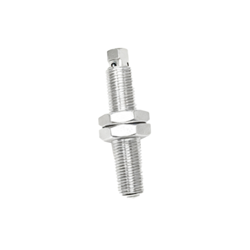
Key Components and Operational Characteristics
The construction of a standard inductive proximity sensor is robust. The core components include a ferrite core with a coil, an oscillator, a trigger circuit, and an output switching device. The sensing face is often made of a wear-resistant material like PTFE or ceramic to protect the internal coil. A critical specification is the nominal sensing distance (Sn), which is the rated operating distance under standardized conditions using a defined target (usually mild steel). It is vital to note that the actual sensing distance can vary with different metals. For instance, stainless steel may reduce the sensing range to about 60-80% of Sn, while copper or aluminum can reduce it to 30-50%. Other key characteristics include repeatability, which defines the precision of detection, and the switching frequency, which determines how fast an object can pass by and still be reliably detected. Most modern sensors also feature built-in protection against short-circuits, overload, and reverse polarity.
Primary Advantages in Industrial Settings
The adoption of inductive proximity switches is widespread due to several compelling advantages. Their non-contact nature eliminates mechanical wear, leading to a virtually infinite operational life concerning switching cycles. They are highly resistant to environmental contaminants such as dirt, grease, and coolants, especially those with high IP (Ingress Protection) ratings. They offer high switching speeds, often in the kilohertz range, making them suitable for high-speed counting or positioning tasks on production lines. Furthermore, they are inherently self-contained, solid-state devices with no moving parts, resulting in excellent shock and vibration resistance. Their output is a clean, bounce-free electrical signal, ideal for interfacing directly with programmable logic controllers (PLCs), counters, or other control systems.
Common Application Examples
Inductive proximity sensors find utility in countless automation scenarios. A classic application is end-position detection on cylinders or linear actuators, confirming whether a piston is fully extended or retracted. They are indispensable in conveyor systems for part presence verification, object counting, and jam detection. In machine tools, they are used for tool breakage detection, spindle positioning, and pallet clamping confirmation. Rotary speed monitoring on shafts or gears is another common use, often achieved by detecting the teeth of a gear. They also serve in safety circuits, though not as primary safety devices, by monitoring guard door positions or verifying the correct placement of workpieces in stamping or welding machines before a cycle begins.
Critical Selection and Installation Guidelines
Selecting the correct inductive sensor requires careful consideration of several parameters. First, identify the target material and size; the target should be larger than the sensor's face for reliable detection. The required sensing distance must be chosen with a safety margin, typically 70-80% of the nominal range, to account for temperature drift and supply voltage variations. The housing style (tubular, rectangular, ring-shaped) must suit the mechanical mounting constraints. Output type is crucial: PNP (sourcing) or NPN (sinking) transistor outputs must match the input card of the controller. Wiring is straightforward, typically involving brown (24VDC+), blue (0V), and black (output) wires. For installation, ensure metallic mounting brackets or surrounding metal structures are not within the sensor's lateral sensing field, as this can cause false triggering. Maintaining a minimum clearance between sensors and between the sensor and the target is essential for stable operation.