Understanding Photoelectric Sensor Fundamentals
Photoelectric sensors are ubiquitous in industrial automation, serving as the eyes of countless machines. Their operation is based on a simple principle: a light emitter sends a beam (visible, infrared, or laser) towards a receiver. The sensor detects changes in this received light, such as interruption or reflection, to determine the presence, absence, or position of an object. The core components are the light source (typically an LED or laser diode), the photodetector (like a phototransistor), and the associated signal processing circuitry. This elegant simplicity, however, exists within harsh industrial environments, which directly influences their reliability and potential failure modes.
Common Causes of Photoelectric Sensor Failure
While generally robust, photoelectric sensors are not immune to failure. The primary culprits are often environmental and application-related. Contamination is a leading cause; dust, oil mist, or debris can coat the lens, attenuating the light beam and causing false signals or a complete loss of detection. Mechanical damage from impacts, excessive vibration, or misalignment can physically break components or shift the optical path. Electrical issues, including voltage spikes, incorrect wiring, or sustained operation outside the specified voltage range, can damage internal electronics. Furthermore, the light source itself has a finite lifespan, though LEDs are rated for tens of thousands of hours. Incompatibility with the target object, such as detecting a transparent or highly reflective surface without proper sensor type selection, can also manifest as a functional failure.
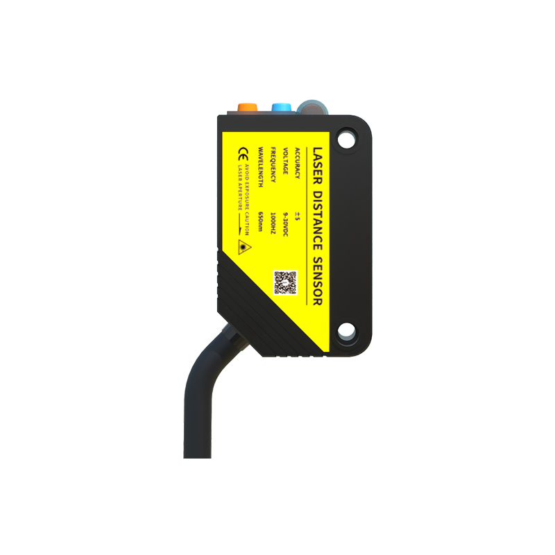
Environmental Stressors and Longevity Impact
The operating environment critically dictates sensor lifespan. Extreme temperatures can cause condensation on lenses, affect electronic component performance, and accelerate material degradation. Sensors exposed to direct, intense ambient light (like sunlight or welding arcs) may experience optical interference, saturating the receiver. Chemical exposure from solvents or corrosive vapors can degrade housing materials and lens clarity. Continuous high-frequency switching can induce thermal stress on internal components. Manufacturers specify Ingress Protection (IP) and NEMA ratings for a reason; selecting a sensor with an IP rating insufficient for the application's dust and moisture levels is a common precursor to premature failure.
Enhancing Reliability Through Proper Selection
Preventing failure starts at the selection stage. The first step is choosing the right sensing mode: through-beam (for longest range and high reliability), retro-reflective, or diffuse reflective. Material and color of the target object must be considered. For challenging conditions, sensors with background suppression or polarized filters are essential. The housing material (e.g., stainless steel for washdown areas) and the correct IP rating (e.g., IP67 for dust-tight and temporary immersion) are non-negotiable for harsh environments. Always consult the datasheet for operational limits regarding temperature, voltage, and load current. Investing in a higher-grade sensor designed for the specific environmental challenge is more cost-effective than frequent replacements.
Installation and Maintenance Best Practices
Correct installation is paramount for longevity. Ensure secure mounting to minimize vibration. Precisely align through-beam and retro-reflective sensors; even slight misalignment reduces signal strength. Use protective conduits for cables in high-traffic areas. Maintain a clean lens through regular, scheduled maintenance using appropriate cleaners. Allow for sufficient cooling space and avoid installing sensors near heat sources. Implement electrical protection such as surge suppressors on the power line in areas prone to spikes. Periodically verify sensor performance and alignment as part of preventative maintenance routines. A well-installed and maintained sensor can operate reliably for many years beyond its expected service life.
Troubleshooting and Diagnostic Indicators
Most modern photoelectric sensors feature built-in diagnostic aids. A stable LED indicator typically signifies normal operation, while a blinking light often indicates issues like weak signal strength, marginal alignment, or power problems. Complete indicator failure suggests an electrical fault. Use an ammeter to check the output current or a voltmeter to verify switching. For analog sensors, monitor the output signal for drift. When troubleshooting, systematically isolate the problem: check power supply, inspect the lens for contamination, verify target properties, and confirm alignment. Swapping the sensor with a known-good unit is a quick way to confirm if the issue is sensor-based or external.
Conclusion: Are They Inherently Prone to Failure?
Photoelectric sensors are not inherently "bad" or prone to failure. They are precision electro-optical devices. Their reliability is overwhelmingly a function of correct selection, proper installation, and adherence to environmental limits. In a controlled, clean environment with appropriate electrical protection, a quality photoelectric sensor can provide millions of reliable operations. Failures are most often the result of application error—using the wrong sensor for the job or exposing it to conditions beyond its design specifications. With informed engineering choices and routine care, photoelectric sensors prove to be exceptionally dependable workhorses in automation.