Understanding the Proximity Sensor Test Bench
A proximity sensor test bench is a specialized piece of equipment designed for the calibration, verification, and functional testing of various types of proximity sensors, including inductive, capacitive, and ultrasonic models. Its primary function is to simulate real-world operating conditions in a controlled laboratory or workshop environment. The bench typically consists of a stable platform, a precision motion system (often with micrometer adjustments), a target mounting fixture with various material samples (e.g., steel, aluminum, brass, plastic), and an integrated measurement unit. This unit connects to the sensor under test and displays critical parameters such as switching distance, hysteresis, repeatability, and output signal integrity. Understanding the layout and capabilities of your specific test bench model is the foundational step before proceeding with any sensor evaluation.
Pre-Operational Safety and Setup Procedures
Before powering the test bench, a thorough safety and setup check is mandatory. Ensure the bench is placed on a stable, vibration-free surface away from strong electromagnetic interference sources. Verify that all electrical connections, including the main power supply to the bench and the connections for the sensor's power and signal outputs, are secure and match the voltage and current ratings specified in the sensor and bench manuals. Install the appropriate target material on the fixture, corresponding to the sensor type being tested—ferrous metal for inductive sensors, various materials for capacitive sensors. Power on the test bench control unit and allow it to complete its initialization sequence. Familiarize yourself with the control software or interface panel, noting the functions for controlling target movement, setting measurement parameters, and logging data.
Mounting and Connecting the Sensor Under Test
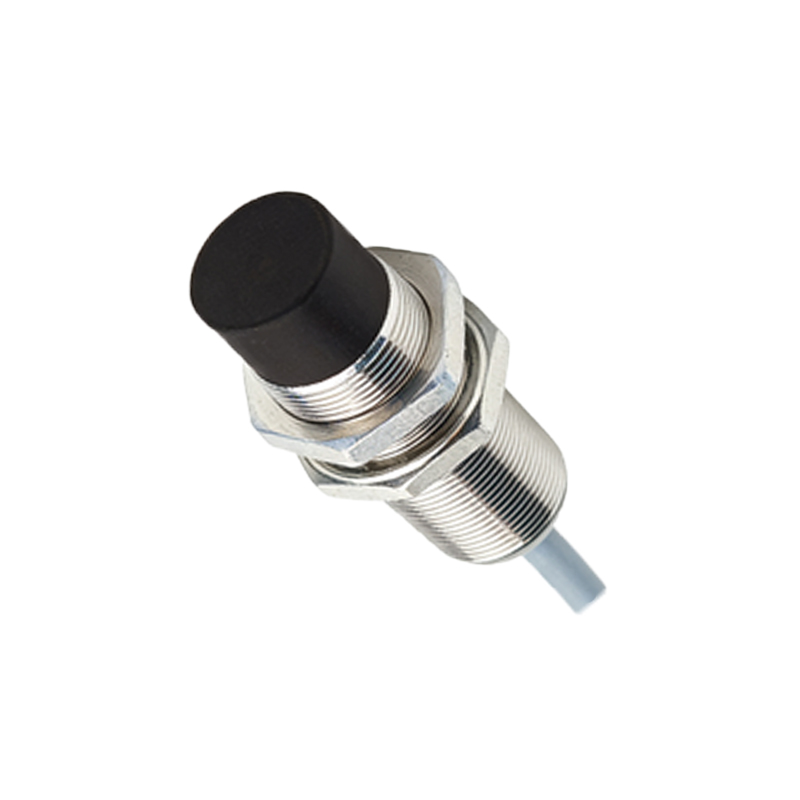
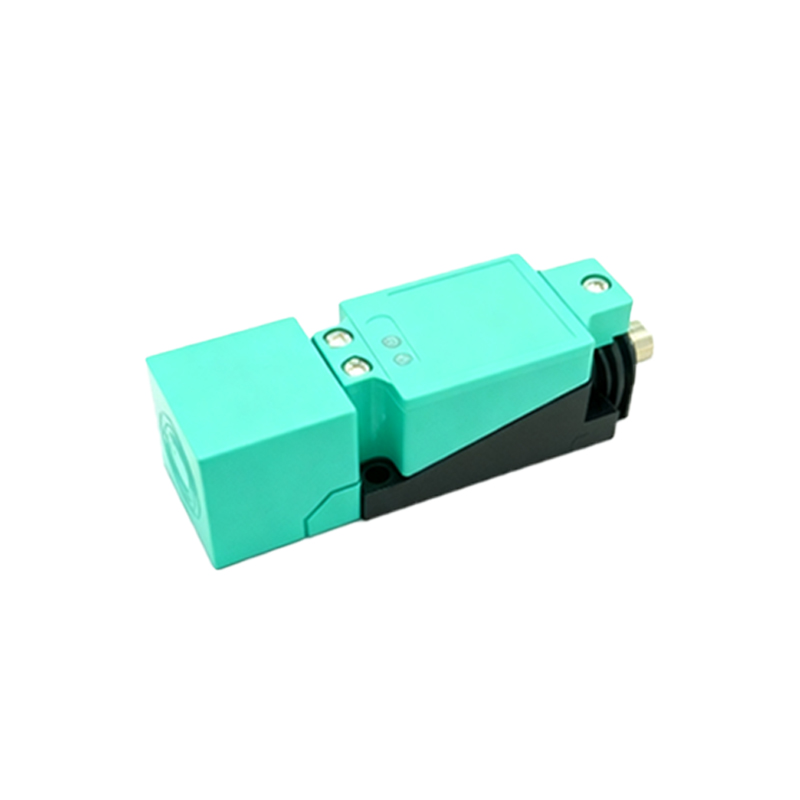
Correct sensor mounting is critical for accurate results. Securely fasten the proximity sensor to the adjustable holder on the test bench, ensuring its sensing face is parallel to the target surface. Even a slight angular misalignment can significantly affect the measured switching point. For barrel-style sensors, use the correct mounting nuts; for block-style sensors, ensure they are flush and stable. Once mounted, connect the sensor's wiring to the test bench's terminal block or quick-connect interface. Typically, this involves connecting the supply voltage (e.g., 10-30V DC), the ground, and the output signal line (PNP/NPN, NO/NC) to the bench's monitoring circuits. Double-check the wiring against the sensor's datasheet to prevent damage from incorrect polarity or voltage.
Executing the Standard Measurement Sequence
With the sensor powered and connected, begin the core measurement procedure. Using the bench's manual or automated control, slowly move the target towards the sensor's sensing face from outside its nominal sensing range. Monitor the bench's display for the state change of the sensor's output. The point at which the output switches (e.g., from 0V to 24V for a PNP sensor) is the "operating point." Precisely note the distance displayed by the bench's position encoder. Continue moving the target until it is at the mechanical minimum, then slowly reverse direction, moving the target away from the sensor. The point where the output switches back to its original state is the "release point." The difference between the operating point and the release point is the sensor's hysteresis. Repeat this approach-and-retract cycle multiple times (e.g., 5-10 times) to calculate the repeatability, which is the statistical variation in the operating point.
Analyzing Key Performance Parameters
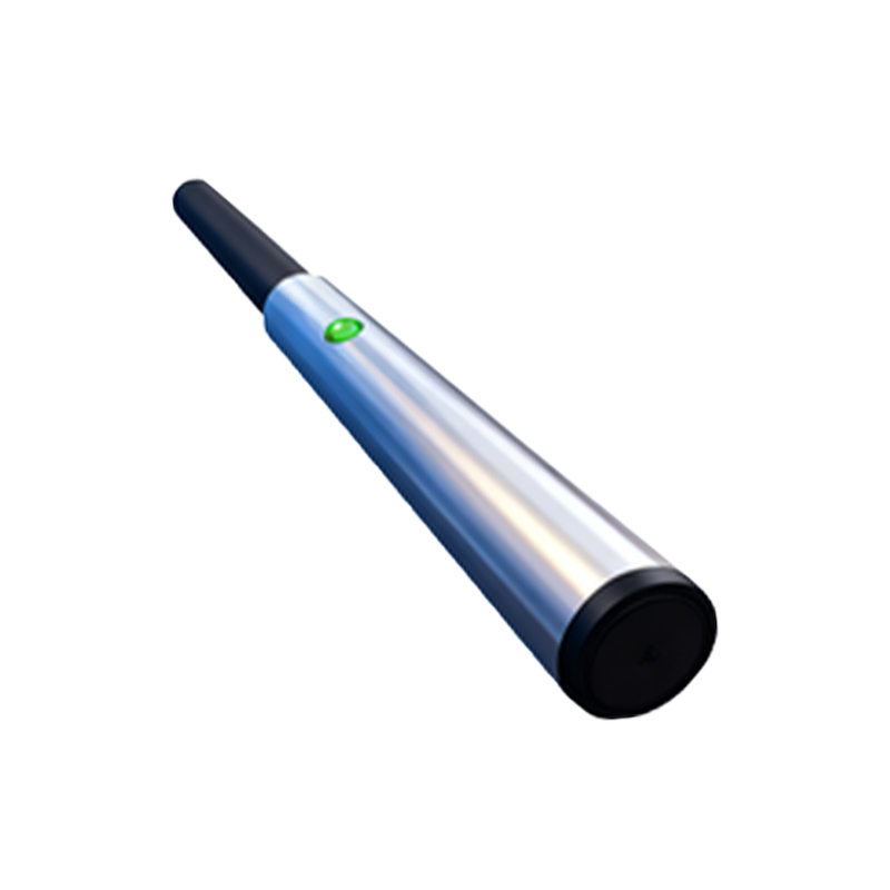
The test bench software or display will provide raw data from the measurements. Key parameters to analyze include: Actual Switching Distance (Sn): The measured operating point under specified conditions, which should be compared to the sensor's nominal sensing range. Hysteresis: Expressed as a percentage of the actual switching distance, a certain hysteresis is normal and prevents output chatter when a target is at the threshold. Repeatability: A crucial indicator of sensor quality and stability, typically required to be within a very small percentage (e.g.,<1%) of the actual switching distance. Additionally, monitor the output signal's rise time, fall time, and voltage levels to ensure they meet the specifications for the connected control system (e.g., a PLC input module).
Data Logging and Calibration Adjustment
Modern test benches often feature data logging capabilities. Use this function to record the measurement results for each sensor tested, creating a traceable quality record. This log should include sensor model, serial number, test date, ambient temperature, measured parameters, and pass/fail status against predefined tolerances. For sensors with calibration potentiometers (e.g., for sensitivity or time delay adjustment), the test bench provides the perfect environment for precise tuning. Based on the measured switching distance, you