Understanding the Proximity Switch System
A typical industrial proximity switch system comprises three primary components: the sensor itself, the processing/control unit (often with a display screen), and the connected load or machine. The sensor detects the presence or absence of a target object and sends a corresponding signal. This signal is processed by the control unit, which then provides visual feedback on its screen and triggers the required output action. When the sensor's indicator LED is illuminated but the main control screen remains blank, it indicates a partial system failure. The problem is isolated to the communication path between the sensor and the display, or within the display unit's own circuitry and power supply.
Initial Power Supply Verification
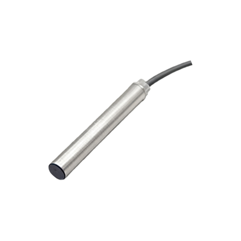
Begin troubleshooting by systematically checking the entire power delivery chain. Confirm that the main power source to the control cabinet is stable and within the specified voltage range. Use a multimeter to verify voltage at the primary input terminals of the power supply unit (PSU) feeding the controller. Next, measure the output voltage of this PSU. A screen failure is frequently caused by an insufficient or absent DC voltage supply specifically to the display module. Even if the sensor receives enough power to light its LED (which often requires minimal current), the display screen may have a higher power requirement that is not being met. Check for loose connections, blown fuses on the display circuit, or a faulty internal DC-DC converter dedicated to the screen.
Inspecting Wiring and Communication Links
A lit sensor LED confirms local sensor power and basic detection function. The fault may lie in the signal transmission path. For digital sensors, check the wiring of the signal output line (often black or blue wire) back to the controller's input card. A broken wire, poor crimp, or corroded terminal can prevent the signal from reaching the processor, meaning no data is available to display. For networked or bus-based systems (e.g., PROFINET, IO-Link), verify the health of the network cable and connectors. The sensor might be powered and active on the network, but a communication fault can prevent status data from populating the human-machine interface (HMI) or screen. Inspect the controller's communication module status indicators for errors.
Analyzing Controller and Display Unit Faults
If power and wiring are confirmed correct, the issue likely resides within the controller or its display sub-assembly. A processor fault or corrupted firmware can cause the main program to halt, leaving peripherals like sensor input cards active but the display driver inactive. Attempt a controlled power cycle of the entire controller. Listen for audible alarms or observe other status LEDs on the controller chassis. In some units, the display is a separate module connected via an internal ribbon cable. This cable can become dislodged or fail. The display backlight itself may have failed, making the information invisible unless viewed with a bright light at an angle—a sign the LCD is receiving data but not illuminated.
Sensor Output Configuration Mismatch
While less common, a configuration error can manifest as a blank screen. Some advanced systems are programmed to show specific screens or data only upon a validated sensor signal of a certain type or from a specific address. If the sensor's output type (e.g., NPN vs. PNP) is incompatible with the controller's input circuit, the controller may not register the signal correctly. Similarly, if a programmable sensor has an incorrect output delay or pulse width setting, the signal might be too brief for the controller's input scan time to capture, resulting in no update to the display. Verify the sensor and controller input specifications and parameter settings match the application requirements.
Systematic Troubleshooting Procedure
Follow a logical sequence to isolate the fault efficiently. Step 1: Verify control cabinet main power and PSU output. Step 2: Check all fuses related to the controller and display. Step 3: Inspect the sensor's signal wiring continuity and connection integrity at both ends. Step 4: Monitor the controller's input LED corresponding to the sensor channel; does it illuminate when the sensor activates? Step 5: If the input LED lights but the screen is blank, focus on the controller/display unit. Check for separate display power connections. Step 6: Consult the controller's diagnostic menu or software, if accessible via another interface, for error logs. Step 7: If possible, temporarily substitute a known-working display module or controller to confirm the fault location.
Preventive Maintenance Recommendations
To prevent recurrence, implement a robust maintenance schedule. Regularly inspect and tighten all electrical connections to prevent thermal cycling from causing loosening. Use a power line monitor to log voltage quality and detect sags or transients that can damage