Understanding Photoelectric Sensor Sensitivity
Photoelectric sensors are critical components in automation and control systems, detecting the presence, absence, or distance of objects using a light beam. When a sensor becomes insensitive or exhibits a weak response, it fails to reliably detect targets, leading to production errors, machine downtime, and safety concerns. Insensitivity typically manifests as missed detections, intermittent operation, or a reduced effective sensing range. Before attempting any adjustment, it is crucial to understand that sensitivity issues can stem from various factors, including environmental contamination, misalignment, power supply problems, or component aging. A systematic approach to troubleshooting and adjustment is essential for restoring optimal performance and ensuring system integrity.
Initial Inspection and Safety Precautions
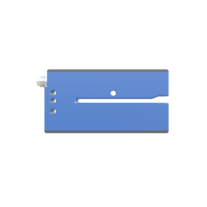
Always begin by following proper lockout-tagout (LOTO) procedures to de-energize the associated machinery and ensure a safe working environment. Visually inspect the sensor and its lens for accumulations of dust, dirt, oil, or moisture, which are primary culprits for scattering or attenuating the light beam. Clean the lens gently with a soft, lint-free cloth and an appropriate cleaner, such as isopropyl alcohol. Simultaneously, inspect the target object; its color, surface finish, size, and material can dramatically affect reflectivity and, consequently, the sensor's response. Ensure the target is within the sensor's specified range and that its characteristics match the sensor's design parameters. Verify all mechanical mounting points are secure, as vibration can cause misalignment.
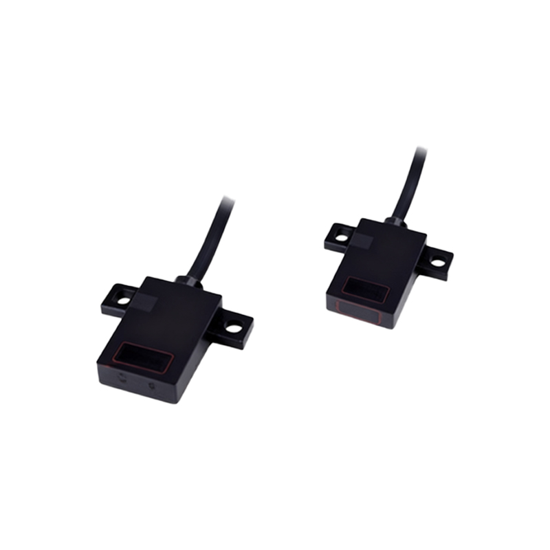
Verifying Electrical Connections and Power
An unstable or incorrect power supply is a common source of perceived insensitivity. Using a multimeter, confirm that the voltage at the sensor's terminals matches its rated specification (e.g., 10-30 VDC). Check for voltage drops under load, which can indicate inadequate wiring gauge or a failing power supply. Inspect all wiring connections for corrosion, looseness, or damage. For sensors with separate amplifier units, ensure the cable between the sensor head and the amplifier is intact and properly connected. A fluctuating power source can cause erratic behavior that mimics low sensitivity. Also, verify the load connected to the sensor's output is within its maximum current rating.
Optimizing Alignment and Optical Path
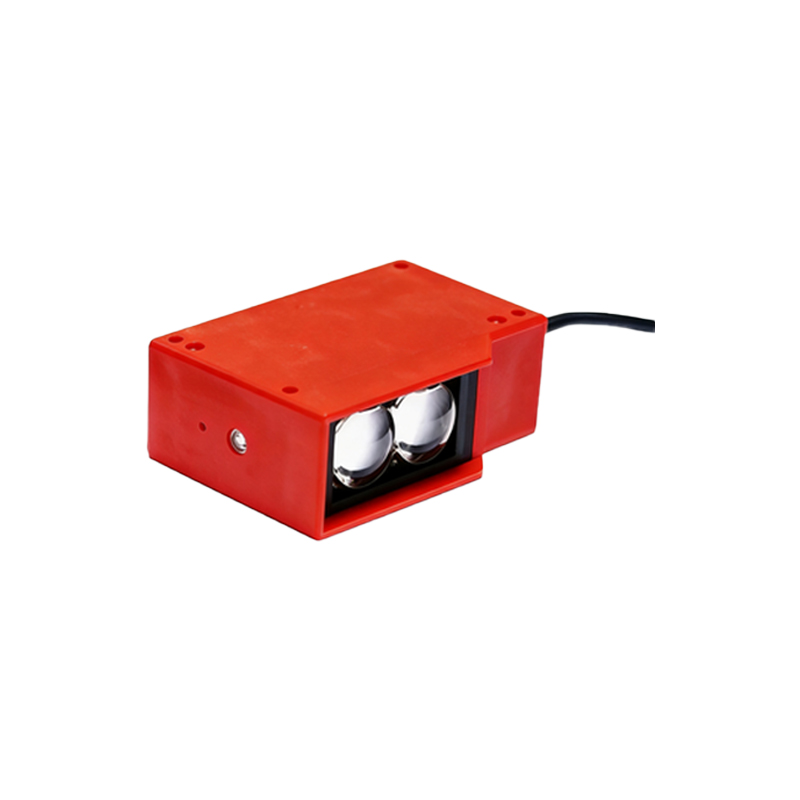
Misalignment is a frequent issue, especially with through-beam and retro-reflective sensors. For through-beam types, carefully align the emitter and receiver until the alignment indicator (often an LED) signals optimal reception. Use precision tools if necessary. For retro-reflective sensors, ensure the reflector is clean and correctly aligned. For diffuse reflective sensors, the alignment is less critical, but the sensor must be positioned at the correct angle and distance relative to the target. Eliminate any obstructions in the optical path. Be aware of background objects that might reflect stray light, potentially causing false triggers or desensitizing the sensor. Adjust the sensor's position to avoid such optical noise.
Utilizing the Sensitivity Adjustment Mechanism
Most modern photoelectric sensors feature a sensitivity potentiometer, a teach-in button, or digital parameter settings. The potentiometer is adjusted using a small screwdriver. To calibrate, introduce the target object to the sensing field and slowly adjust the potentiometer counter-clockwise to decrease sensitivity until the output just deactivates. Then, rotate it clockwise to increase sensitivity until the output reliably activates, and continue an additional 10-15% to establish a safe margin. For sensors with teach-in functions, follow the manufacturer's procedure, which typically involves pressing a button when the target is present and again when it is absent. This auto-sets the threshold. Digital sensors allow fine-tuning via software, enabling precise setting of thresholds, timers, and hysteresis to combat environmental drift.
Addressing Environmental Interference
Ambient light from factory lighting, sunlight, or other machinery can saturate a sensor's receiver. Install physical shrouds or shades to block stray light. Consider switching to a modulated (pulsed) light sensor, which is immune to constant ambient light. For sensors in harsh environments, ensure the housing's IP rating is adequate. Electrical noise from motors, drives, or welders can interfere with signal processing. Use shielded cables, ensure proper grounding, and separate sensor wiring from high-power lines. In applications with airborne contaminants like steam or smoke, select sensors with designed compensation or use a purging system to keep the lens clear.
Evaluating Sensor Selection and Final Testing
If sensitivity issues persist after exhaustive adjustment, the sensor itself may be failing or may be fundamentally unsuitable for the application. Aging LEDs emit less light, and receivers lose responsiveness over time. Consider the sensing mode: a difficult-to-detect target (e.g., transparent, dark, or small) might require a different technology. A through-beam sensor offers the longest range and highest excess gain for challenging targets, while a polarized retro-reflective sensor can ignore shiny surfaces. After all adjustments, conduct rigorous testing. Cycle the target through the sensing zone repeatedly at the required speed and distance. Monitor the output with an oscilloscope or PLC to verify clean, consistent switching with no missed or false signals. Document the final settings for future reference.