Understanding the Components: Photoelectric Sensor and Solenoid Valve
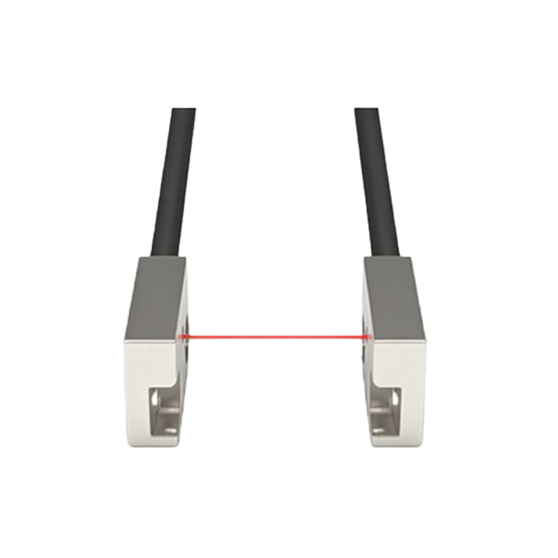
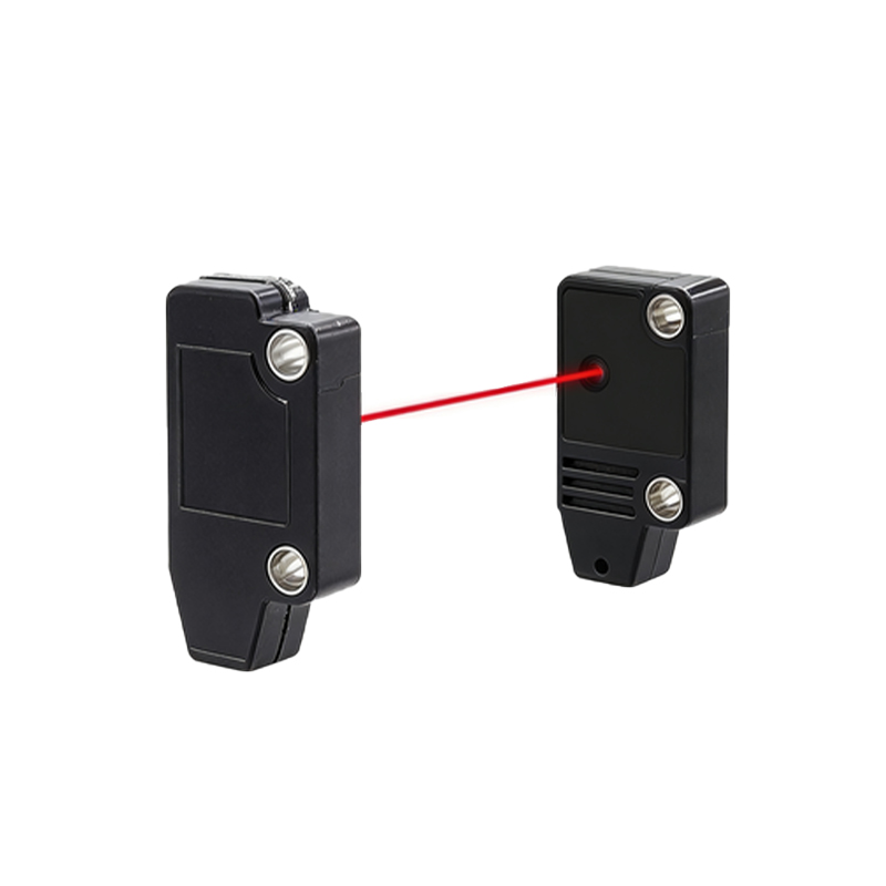
A photoelectric sensor is a device that uses a light transmitter and receiver to detect the presence, absence, or distance of an object. Common types include through-beam, retro-reflective, and diffuse reflective sensors. They typically provide a discrete output signal, either a PNP (sourcing) or NPN (sinking) transistor switch. A solenoid valve is an electromechanically operated valve that controls the flow of liquid or gas. It consists of a coil, plunger, and valve body. When energized, the coil creates a magnetic field that moves the plunger, opening or closing the valve. The key to connecting them is using the sensor's output to control the power circuit for the solenoid coil.
Fundamental Electrical Principles and Safety First
Before any wiring begins, paramount importance must be placed on safety. Always disconnect and lock out all power sources. Verify the voltage and current ratings of both the photoelectric sensor and the solenoid valve. Mismatched voltages can cause immediate failure or create hazardous conditions. The sensor's output current rating must be sufficient to handle the inrush and holding current of the solenoid coil. If not, an intermediate relay is absolutely necessary. Gather appropriate tools: wire strippers, crimpers, screwdrivers, and a multimeter for verification. Plan the circuit layout considering wire gauge, conduit requirements, and environmental factors like moisture or vibration.
Wiring Configuration: Using a DC Power Supply
A typical 24V DC system is most common in industrial control panels. For a setup with a PNP (sourcing) sensor, follow these steps. First, connect the positive terminal (+24V) of the power supply to the sensor's brown (or red) wire (V+). Connect the power supply negative (0V) to the sensor's blue wire (V- or common). The sensor's black (or white) wire is the switched output. This wire will carry the +24V signal when the sensor is active (object detected). Connect this black output wire directly to one terminal of the solenoid valve coil. Finally, connect the other terminal of the solenoid coil back to the power supply's 0V (negative) terminal. This completes the circuit. When the sensor detects an object, its output transistor switches on, sending +24V to the coil, energizing the valve.
Wiring Configuration: Using an NPN (Sinking) Sensor
The circuit logic is complementary for an NPN sensor. Connect the power supply positive (+24V) to one terminal of the solenoid coil. Connect the other terminal of the solenoid coil to the black (output) wire of the NPN sensor. Connect the sensor's blue wire to the power supply negative (0V). Connect the sensor's brown wire to +24V. In this configuration, the NPN output acts as a switch to ground (0V). When the sensor activates, its output transistor connects the solenoid coil's circuit to 0V, completing the path to negative and allowing current to flow from +24V, through the coil, through the sensor, to ground. This energizes the valve.
The Critical Role of the Flyback Diode
A solenoid coil is an inductive load. When power is suddenly removed, the collapsing magnetic field generates a high-voltage reverse spike (back EMF). This transient can easily damage the sensitive output transistor inside the photoelectric sensor. To protect the sensor, a flyback diode (also called a freewheeling or suppression diode) must be installed across the solenoid coil terminals. The diode's cathode (striped end) should connect to the positive side of the coil, and its anode to the negative side. This diode provides a safe path for the induced current to dissipate, clamping the voltage spike and protecting the sensor's electronics. This is a non-negotiable component for reliable operation.
When to Use an Intermediate Relay
There are several scenarios where connecting the sensor directly to the valve is not advisable. If the solenoid valve's coil current exceeds the sensor's maximum load current (often around 100-200mA), a relay is required. If the solenoid operates on AC voltage but the sensor output is DC, a relay provides necessary isolation. For controlling multiple valves with one sensor or providing electrical isolation in harsh environments, a relay is the standard solution. Wire the sensor output to energize the relay coil (with its own protection diode). Then, use the relay's heavy-duty contacts to switch the higher-power AC or DC circuit for the solenoid valve. This preserves the sensor's lifespan.
Practical Wiring Example and Troubleshooting Tips
Consider a practical setup: a 24VDC diffuse sensor (PNP) controlling a 24VDC solenoid valve with a 0.5A coil. The sensor's load rating is 0.1A. Since the coil current (0.5A) exceeds the sensor rating, an interposing relay is used. Wire the sensor output to the relay coil (which draws only 40mA). Install a diode across the relay coil. Use the relay's normally open (NO) contact in series with the solenoid valve and the main 24VDC power. For troubleshooting, use a multimeter. Check for presence of power supply voltage. Verify sensor operation by observing its indicator LED. Measure voltage at the output wire when activated. Listen for the relay or valve click. Check continuity of all connections and the health of the protection diode.
System Integration and Best Practices
For robust system integration, consider control logic. Sometimes the valve must open when an object is absent. This requires using the sensor's normally closed (NC) output mode or programming an inverse function in a connected PLC. Use shielded cables for sensors in electrically noisy environments, grounding the shield at one end only. Employ proper strain relief and routing to avoid interference with moving machinery. Label all wires clearly according to the electrical schematic. After wiring, perform a systematic power-on test: first power the sensor alone, then test its output with a meter, and finally energize the full circuit. Document the as-built wiring diagram for future maintenance.