Introduction to Proximity Sensor Wiring
Proximity sensors are indispensable components in modern industrial automation, providing non-contact detection of metallic or non-metallic objects. Their reliability and precision hinge on correct installation and wiring. A fundamental aspect of this is understanding the standard three-wire configuration, which is the most common setup for DC-powered sensors. Unlike two-wire AC/DC sensors that are wired in series with the load, three-wire sensors offer separate paths for power supply and output signal, leading to superior performance, faster switching, and lower leakage current. This configuration is crucial for engineers and technicians to ensure seamless integration into control systems, such as PLCs (Programmable Logic Controllers).
Decoding the Three Wire Colors: Brown, Blue, and Black
Internationally, a color-coding standard (often based on IEC 60947-5-2) is widely adopted to ensure consistency and safety. The three wires are typically brown, blue, and black. The brown wire is universally designated as the positive supply voltage wire (+V). It must be connected to the positive terminal of the DC power source. The blue wire is always the negative supply voltage wire, or common (0V). It connects to the negative terminal or ground of the DC power supply. Finally, the black wire is the output signal wire. This is the critical wire that carries the switching signal from the sensor to the load (e.g., a PLC input, relay, or indicator lamp). It is essential to consult the specific sensor's datasheet, as some manufacturers may use alternative colors like white for the output.
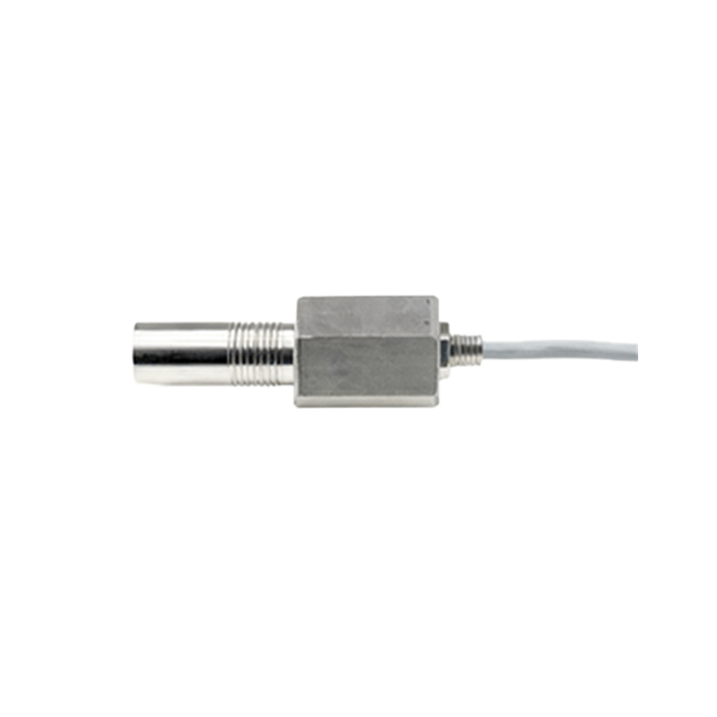
The Core Function: Sourcing (PNP) vs. Sinking (NPN) Outputs
The functionality of the black output wire is defined by the sensor's transistor type, leading to two primary output configurations: PNP and NPN. This is the most critical distinction in three-wire sensor wiring. A PNP sensor, also known as a "sourcing" sensor, switches the positive voltage. In its active state (when an object is detected), the black wire connects the internal load to the positive supply (brown wire), sourcing current to the load. Conversely, an NPN sensor, or a "sinking" sensor, switches the negative side. When active, its black wire connects the load to the negative supply (blue wire), sinking current from the load to ground. The choice between PNP and NPN often depends on the regional standard (PNP is common in Europe, NPN in some Asian countries) and the input configuration of the connected controller.
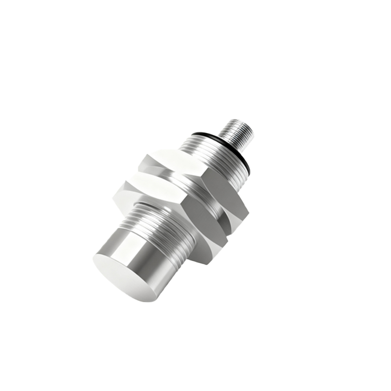
Wiring Diagrams and Practical Connection Examples
Visualizing the connections clarifies the theory. For a PNP sensor connection to a PLC digital input: Connect the brown wire to the DC+ terminal (e.g., 24V), the blue wire to the DC- terminal (0V). The black output wire connects to the PLC input channel. The PLC input module itself must be configured as a sinking input (common terminal connected to 0V). When the sensor detects an object, it sources 24V to the PLC input, registering a HIGH signal. For an NPN sensor: The brown and blue wires connect to power as before. The black wire connects to the PLC input, but the PLC input module must now be configured as a sourcing input (common terminal connected to +24V). Upon detection, the NPN sensor sinks current to ground, pulling the PLC input low to register a signal.
Critical Considerations for Reliable Operation
Correct wiring is paramount, but several other factors ensure long-term reliability. First, always verify the supply voltage range (commonly 10-30V DC) and ensure the polarity is correct; reverse polarity can permanently damage the sensor. Second, consider the load connected to the black wire. Do not exceed the sensor's maximum output current rating. For inductive loads like relays, use a protective flyback diode. Third, pay attention to wiring practices: use shielded cables in electrically noisy environments, keep sensor cables away from power lines, and ensure proper grounding. Finally, understand the output state: many sensors have a normally-open (NO) or normally-closed (NC) logic, determining if the black wire is active when a target is present or absent.
Troubleshooting Common Wiring Issues
When a proximity sensor fails to operate, systematic troubleshooting of the wiring is the first step. Use a multimeter to check for the correct voltage between the brown and blue wires. Next, measure the voltage on the black wire relative to blue (0V). For a PNP sensor in the active state, it should read close to the supply voltage (e.g., 24