Introduction to Photoelectric Sensor Wiring
Photoelectric sensors are indispensable components in modern industrial automation, providing non-contact detection of objects based on light beam interruption or reflection. The wiring of these sensors, particularly the connection of the signal wire often designated as SN (Signal Negative) or simply the signal line, is a fundamental aspect of their installation and operation. Correct wiring ensures reliable performance, prevents damage to the sensor and connected control systems like PLCs (Programmable Logic Controllers), and maintains overall system safety. This guide delves into the specifics of photoelectric sensor wiring, with a focus on understanding the SN terminal and its role in various circuit configurations.
Understanding Sensor Terminal Designations
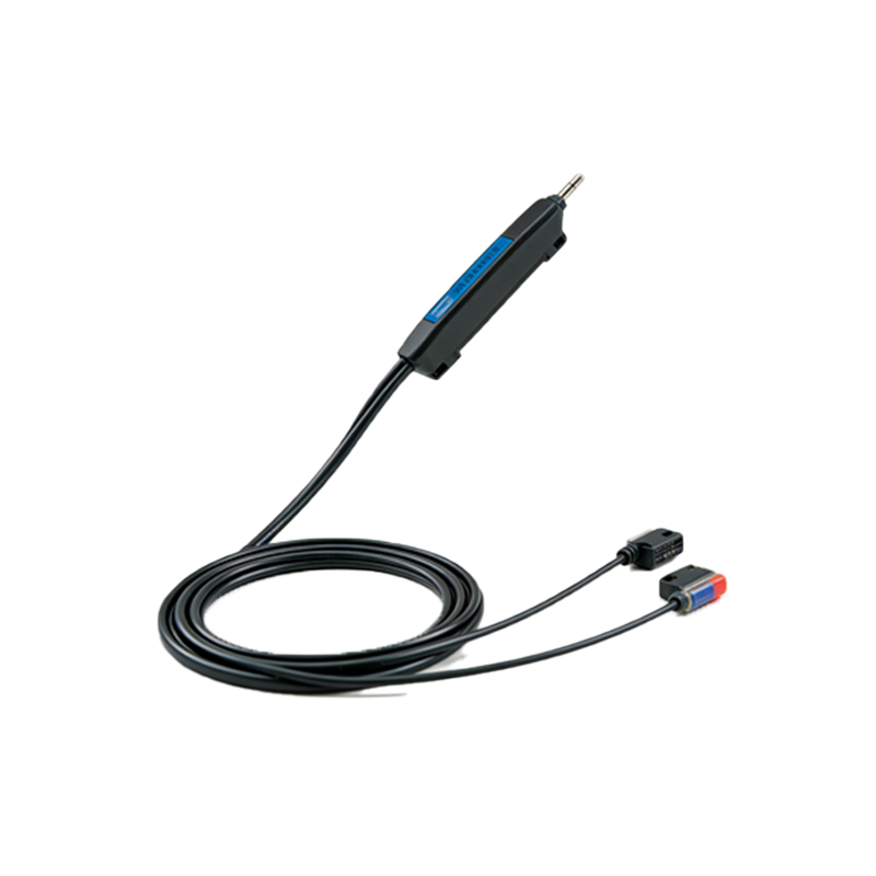
A typical three-wire or four-wire photoelectric sensor will have clearly marked terminals. Common designations include Brown wire for V+ (positive power supply, typically 10-30V DC), Blue wire for V- or 0V (negative power supply/common), Black wire for the output signal, and sometimes a White wire for a complementary output or control input. The Black wire is frequently the core signal line. In many wiring schematics and datasheets, the signal output point connected to the load (like a PLC input) is referenced as the SN point. It is crucial to consult the specific sensor's datasheet, as terminology can vary; SN might explicitly label the signal common or the switched negative side of the output transistor.
Wiring Configurations: NPN vs. PNP Sourcing
The wiring of the SN signal is entirely dependent on whether the sensor has an NPN (sinking) or PNP (sourcing) output transistor. This is the most critical distinction in sensor wiring. An NPN sensor switches the Negative side of the load. In this configuration, the load (e.g., PLC input) is connected between the positive supply (V+) and the sensor's black signal wire (SN). When activated, the NPN transistor sinks current from the load to the common (0V), completing the circuit. Conversely, a PNP sensor switches the Positive side. Here, the load is connected between the sensor's black signal wire (SN) and the common (0V). When activated, the PNP transistor sources current from V+ through the load to common. Misidentifying NPN vs. PNP will result in the sensor failing to operate the load.
Step-by-Step Wiring Procedure
First, always disconnect power before beginning any wiring work. Identify the sensor type (NPN or PNP) from its label or datasheet. For a standard DC three-wire sensor: Connect the Brown wire to the positive DC supply (e.g., +24V). Connect the Blue wire to the negative DC supply (0V/common). The critical step is connecting the Black (SN) signal wire. For an NPN sensor, connect this wire to one side of your load (PLC input terminal). The other side of that load must then be connected to the positive supply (+24V). For a PNP sensor, connect the black wire to one side of your load. The other side of the load must be connected to the common (0V). Always ensure wire gauges are appropriate for the current and use ferrules or proper terminal connections for durability.
Interfacing with PLCs and Control Systems
Most industrial PLCs have input cards designed to accept either sourcing (PNP) or sinking (NPN) signals, but their internal wiring differs. A PLC digital input module configured for sinking (NPN) typically has its input points internally connected to positive voltage, expecting the sensor to connect the point to common (0V). Therefore, an NPN sensor's SN wire is perfect for this. A sourcing (PNP) input card has its points connected to common, expecting a sensor to provide positive voltage, matching a PNP sensor's SN output. Mismatching the sensor type and PLC input type will prevent signal detection. Some sensors offer selectable NPN/PNP output or have both a Black (NPN) and White (PNP) wire, providing flexibility.
Common Wiring Mistakes and Troubleshooting
Several frequent errors occur during sensor wiring. Incorrect power polarity (reversing brown and blue) can instantly destroy a sensor. Confusing NPN and PNP wiring, as described, is the most common functional error. Another mistake is forgetting to complete the circuit by not properly connecting the second side of the load to either V+ or 0V. For troubleshooting, use a multimeter. Check for correct supply voltage between brown and blue wires. With the sensor powered, measure the voltage on the black SN wire relative to blue (0V). For an inactive PNP sensor, it should read near 0V; when active, it should read close to the supply voltage (e.g., 24V). For an inactive NPN sensor, the SN wire voltage is floating or high; when active, it should drop to near 0V.
Shielding and Noise Immunity Considerations
In electrically noisy industrial environments, proper shielding of the signal wire (SN) is essential to prevent false triggering. Many sensors come with a shielded cable where the drain wire or foil shield should be grounded at only one end, typically at the control panel side, to the earth ground or the OV reference of the power supply. This shield protects the internal signal conductors from electromagnetic interference (EMI). Avoid running sensor signal cables in the same conduit or tray as high-power AC lines, motor leads, or variable frequency drive (VFD) cables. Maintaining a clean, stable power supply for the sensors also significantly enhances noise immunity and long-term reliability.
Conclusion and Best Practices
Proper wiring of the photoelectric sensor's SN signal line is a straightforward yet vital task. Always start by identifying the sensor's output type (NPN/PNP) from its documentation. Plan the circuit to match the sensor type with the load's requirements. Use high-quality connectors, secure cable grips on the sensor housing to prevent strain, and adhere to local electrical codes. Implementing good practices like shielding, segregation from noise sources, and correct grounding from the initial installation will maximize sensor lifespan and system uptime. When in doubt, the manufacturer's datasheet remains the ultimate authority for specific wiring instructions and specifications.