Introduction to Gear Proximity Switch Sensors
Gear proximity switch sensors represent a critical component in the realm of industrial automation and motion control. These specialized sensors are designed to detect the presence, absence, or position of gear teeth without any physical contact. Operating on principles such as inductive, magnetic, or capacitive sensing, they generate a signal when a gear tooth passes within their detection range. The non-contact nature of these devices ensures minimal wear and tear, leading to enhanced reliability and longevity in demanding industrial environments. Their primary function is to provide precise feedback on rotational speed, position, and direction, which is fundamental for synchronizing machinery, preventing collisions, and ensuring operational safety.
The Significance of 3D Modeling in Sensor Design
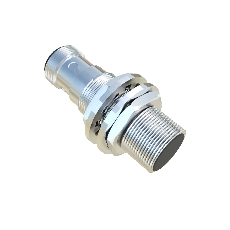
The transition from traditional 2D schematics to sophisticated 3D modeling has revolutionized the design and development of gear proximity switch sensors. Utilizing advanced Computer-Aided Design (CAD) software, engineers can now create highly accurate digital twins of these sensors. This 3D design process allows for comprehensive visualization of the sensor's internal components, housing geometry, and mounting interfaces. Engineers can simulate the sensor's interaction with various gear profiles in a virtual environment, optimizing the sensing distance, alignment, and housing shape to prevent interference. This proactive approach minimizes prototyping costs, accelerates time-to-market, and enables the creation of compact, robust designs tailored for specific spatial constraints within machinery.
Key Design Considerations in 3D
When developing a 3D model for a gear proximity switch, several critical factors must be meticulously addressed. The sensing face geometry is paramount; its contour must be optimized to achieve the desired sensing range and immunity to side-lobe detection from adjacent gear teeth. Material selection, visualized through 3D material libraries, impacts performance—stainless steel housings for corrosive environments or polymer composites for lightweight applications. Mounting provisions, such as bolt holes or threaded barrels, are integrated into the 3D model to ensure secure and repeatable installation. Furthermore, the model must account for environmental sealing (IP ratings), requiring precise O-ring grooves and sealant channels to be designed directly into the housing, ensuring protection against dust, moisture, and coolants.
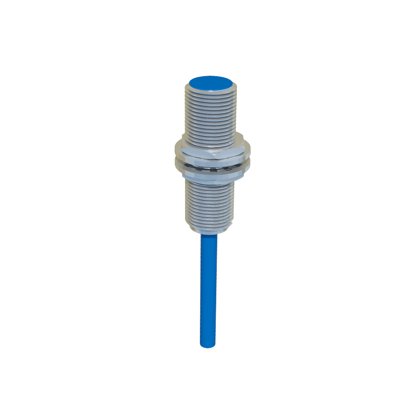
Simulation and Performance Analysis
Modern 3D CAD and CAE (Computer-Aided Engineering) tools empower engineers to conduct in-depth simulations before physical manufacturing. Electromagnetic field simulations can predict the sensor's magnetic or inductive field distribution, ensuring reliable detection of ferrous or non-ferrous gear teeth. Thermal analysis can model heat dissipation, crucial for sensors operating near high-temperature processes. Stress analysis evaluates the structural integrity of the housing under vibration or impact loads. By analyzing these factors in a 3D virtual space, potential failure points are identified and rectified early, resulting in a sensor that delivers consistent performance, high accuracy, and resilience against real-world operational stresses.
Integration and Installation Planning
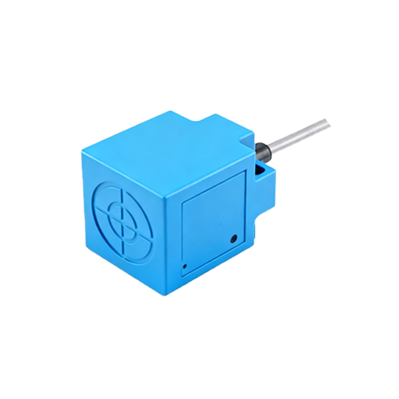
A major advantage of a detailed 3D model is its utility in system integration. The sensor's 3D file can be imported into the larger 3D assembly model of a machine or production line. This allows for precise digital mock-up, where engineers can verify clearances, ensure optimal positioning relative to the gear, and route connecting cables without clashes with other components. Installation teams can use these models for planning, reducing installation errors and downtime. For complex gearing systems, the 3D model helps in determining the ideal sensor orientation—radial, axial, or tangential—to achieve the most reliable pulse signal for the control system.
Applications Across Industrial Sectors
The application of 3D-designed gear proximity switches spans numerous industries. In automotive manufacturing, they monitor the timing and speed of assembly line robots and conveyor drives. In the wind energy sector, they are crucial for monitoring the rotational speed of giant turbine gears within the nacelle. Packaging machinery relies on them for precise registration control, ensuring labels and cuts are made at exact positions. Steel mills and paper plants use these ruggedized sensors to monitor heavy-duty gearboxes, providing essential data for predictive maintenance programs and preventing catastrophic failures.
Future Trends: Digital Twins and Smart Sensors
The future of gear proximity switch sensors is intrinsically linked to their 3D digital identity and connectivity. The 3D model evolves into a living digital twin that receives real-time operational data. Smart sensors with integrated IO-Link or other industrial communication protocols can transmit not just a switch signal, but also diagnostic information like temperature, signal strength, and remaining operational life. The 3D model serves as the visual backbone for this data in Plant Asset Management software, enabling maintenance personnel to visualize the exact sensor's health and location within the machine, ushering in an