Understanding the Components: 5-Wire Sensor and SSR
A 5-wire photoelectric sensor is a versatile device commonly used for object detection in industrial automation. Unlike simpler 2-wire or 3-wire sensors, it provides both a normally open (NO) and a normally closed (NC) output signal simultaneously, along with separate wires for power supply and a common wire. This configuration offers greater flexibility in control logic. A Solid State Relay (SSR) is an electronic switching device that turns on or off when a small external voltage is applied across its control terminals. It uses semiconductor components like thyristors or transistors to perform the switching, offering advantages such as silent operation, fast switching speeds, and long life compared to electromechanical relays. The core of this connection is using the sensor's switched output to control the low-voltage DC input side of the SSR, which in turn safely switches a high-power AC or DC load on its output side.
Wiring Configuration and Color Code Standards
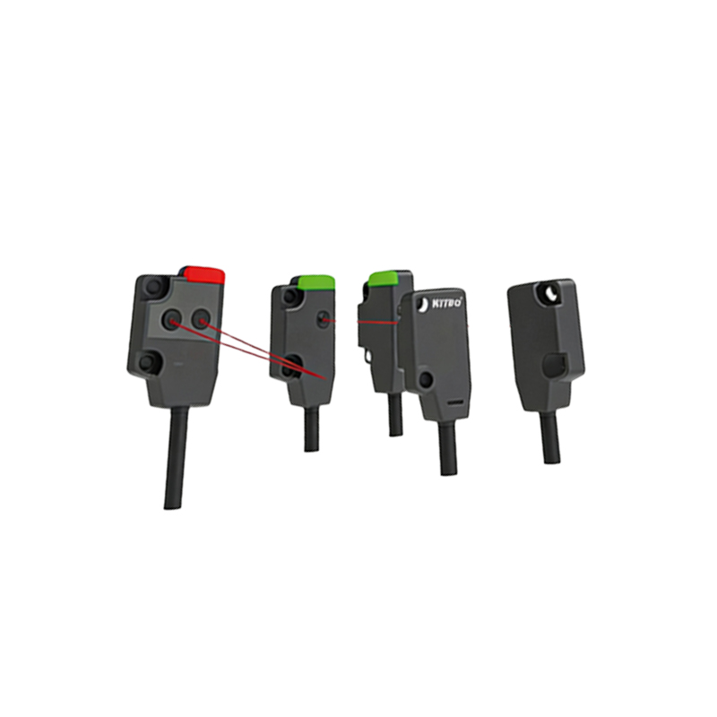
While color codes can vary by manufacturer, a typical 5-wire DC sensor follows a common convention. The brown wire is typically connected to the positive DC supply voltage (often +24V DC). The blue wire is connected to the DC common or 0V (ground). The black wire is usually the normally open (NO) output signal. The white wire is often the normally closed (NC) output signal. The final wire, often gray or another color, is the common terminal for the output signals. It is crucial to always consult the specific sensor's datasheet for the definitive pinout. For the SSR, identify the control (input) terminals, typically labeled as (+) and (-) for DC input models, and the load (output) terminals for connecting the main power and the device to be controlled.
Step-by-Step Connection Procedure
First, ensure all power sources are disconnected. Connect the sensor's power: attach the brown wire to the positive terminal of your 24V DC power supply and the blue wire to the negative terminal. Next, prepare the SSR control circuit. You will use either the NO or NC output from the sensor, depending on your desired logic. For a standard "detect-then-activate" operation, use the black (NO) wire. Connect the sensor's output common wire (e.g., gray) to the positive side of your control power source (this can often be the same +24V line). Then, connect the chosen signal wire (black for NO) to the positive (+) control terminal of the SSR. Finally, connect the negative (-) control terminal of the SSR back to the 0V/negative of the power supply. This completes the control loop.
Completing the Power Circuit with the SSR
On the load side of the SSR, you will switch the main power for your equipment, such as a motor, heater, or solenoid. Connect one wire of your AC or DC load power source to one of the SSR's output terminals. Connect the other SSR output terminal to one terminal of the load device (e.g., a motor). The other terminal of the load device is then connected back to the other side of the power source. It is critical to select an SSR with a voltage and current rating that exceeds the requirements of your load. Always use appropriate fuses or circuit breakers for protection on both the control and load sides of the circuit.
Operational Logic and Functionality Testing
With the wiring complete, apply power to the sensor's circuit. When the photoelectric sensor detects an object in its sensing range, its internal output transistor switches. If you used the NO (black) wire, this action closes the circuit between the output common and the NO wire, allowing current to flow into the SSR's control input. This small DC signal activates the SSR's internal electronics, causing it to switch ON and conduct power through its output terminals to your load. The load device turns on. When the object moves away, the sensor's NO output opens, current stops flowing to the SSR control, and the SSR switches OFF, cutting power to the load. Using the NC (white) wire would reverse this logic.
Key Advantages and Practical Applications
This setup combines the non-contact, precise detection capability of photoelectric sensors with the robust, fast, and reliable switching of SSRs. It eliminates the mechanical wear and contact bounce associated with using traditional relays, leading to higher reliability and longer system lifespan. Common applications include automated packaging lines where a detected item triggers a sealing mechanism via an SSR, conveyor sorting systems, automated assembly stations, and safety interlock systems. The electrical isolation between the sensor/control circuit and the high-power load circuit also enhances safety and reduces electrical noise interference.
Essential Safety and Troubleshooting Tips
Always adhere to local electrical codes and safety standards. Use proper wire gauges for the expected current. Ensure the SSR is mounted on a suitable heatsink if switching high currents to prevent overheating. For troubleshooting, use a multimeter to verify the sensor is receiving correct voltage and that its output LED indicates proper detection. Check for the presence of the control signal voltage (e.g., 24V DC) at the SSR input terminals when the sensor is activated. If the control signal is present but the load does not energize, verify the load wiring, fuse integrity, and that the load itself is functional. Double-check that the SSR's output ratings match your load type (AC vs. DC).