Understanding the Components: Sensor and Relay
A photoelectric sensor is a device that uses light to detect the presence, absence, or distance of an object. Common types include through-beam, retro-reflective, and diffuse reflective sensors. They typically output a control signal, most often a DC voltage in a discrete format (like 24V DC for ON state, 0V for OFF). A relay module is an electrically operated switch. It uses a low-power signal from a control device (like our sensor) to control a higher-power circuit, such as turning on a motor, solenoid, or indicator lamp. The relay provides electrical isolation between the sensor's control circuit and the load's power circuit, which is crucial for safety and preventing interference.
Wiring Configuration: Sourcing vs. Sinking
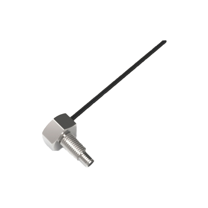
Before connecting wires, it is critical to identify the sensor's output type. A sourcing (PNP) sensor switches the positive voltage to the output wire when activated. A sinking (NPN) sensor switches the negative or ground to the output wire. Most relay module control inputs are designed to work with a sourcing (PNP) signal. For a standard 24V DC system with a sourcing sensor: connect the sensor's positive (brown) wire to 24V DC+, the negative (blue) wire to DC common (0V). The sensor's output (black) wire then connects to one side of the relay module's control input. The other side of the relay's control input is connected back to DC common (0V). This completes the circuit, allowing current to flow from the sensor, through the relay coil, to common, activating the relay when the sensor detects an object.
Practical Connection Steps and Diagram
First, ensure all power is disconnected. Prepare your DC power supply (e.g., 24V), photoelectric sensor, and relay module. Connect the power supply's positive terminal to the sensor's V+ and the relay module's VCC/Positive terminal. Connect the power supply's negative/common terminal to the sensor's V- and the relay module's GND/Negative terminal. Now, connect the sensor's signal output wire to the relay module's signal input terminal (often labeled IN, SIG, or S). Finally, connect the load (e.g., a motor starter coil) to the relay's switched output terminals (NO-COM or NC-COM). Double-check all connections against the manufacturers' datasheets. A simple mental diagram: Power Supply (+) -> Sensor V+ & Relay V+. Power Supply (-) -> Sensor V- & Relay GND. Sensor Output -> Relay IN. Relay COM/NO -> Load -> Power Supply (-).
Load Connection and Relay Contacts
The relay module's output consists of physical switch contacts: Common (COM), Normally Open (NO), and Normally Closed (NC). For most applications where you want the load to turn ON when the sensor detects an object, you will wire the load between the COM and NO terminals. Connect one wire from your load (e.g., a pump) to the COM terminal. Connect the other wire from the load to the positive side of its own power source. The negative side of the load's power source is then connected to the NO terminal on the relay. When the sensor activates, the relay coil energizes, the contacts close (connecting COM to NO), and current flows to power the load. Always ensure the relay's contact rating (voltage and current) exceeds the requirements of your load.
Testing, Troubleshooting, and Safety
After wiring, apply power. Actuate the sensor (place an object in its detection range). You should hear an audible click from the relay module and see its indicator LED illuminate. The connected load should activate. If it does not, follow a systematic approach: Verify power is present at the sensor and relay module using a multimeter. Check if the sensor's output LED turns on when actuated. Measure the voltage between the relay's signal input and common; it should match the sensor's output voltage (e.g., ~24V) when active. Ensure the load is wired correctly and functional independently. Key safety precautions include always locking out/tagging out power before wiring, using proper wire gauges, securing connections, and installing fuses or circuit breakers on both the control and load power lines to protect against short circuits.
Advanced Considerations and Applications
For more complex setups, consider using a relay module with an opto-isolator for superior noise immunity in electrically noisy industrial environments. Some sensors have a relay output built-in, but an external module is preferred for handling larger loads. Time-delay relay modules can be integrated to add on/off delay functions based on sensor triggers. This sensor-relay combination forms the backbone of countless automated systems: conveyor belt control (sensor detects box, relay starts a pusher mechanism), automated packaging lines, safety light curtain interfaces, and inventory counting systems. Understanding this fundamental interconnection empowers engineers to design robust and reliable control logic for diverse industrial automation tasks.