Introduction to Diffuse Photoelectric Sensors
Diffuse photoelectric sensors, also known as diffuse reflective sensors, are widely used in industrial automation for object detection without physical contact. These sensors operate by emitting a light beam, typically infrared or visible light, which reflects off a target object and returns to the receiver. Unlike retro-reflective or through-beam sensors, diffuse sensors rely on the object itself to reflect light, making them versatile for various applications, such as packaging, material handling, and assembly lines. Their design includes key components like an emitter, receiver, and output circuitry, with wire connections playing a critical role in functionality. Among these wires, the blue wire often serves a specific purpose that is essential for proper sensor operation and integration into control systems.
Role of the Blue Wire in Sensor Wiring
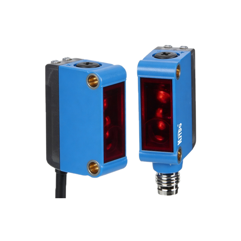
In many diffuse photoelectric sensors, the blue wire is designated as the common or neutral wire, particularly in DC-powered models. This wire completes the electrical circuit, allowing current to flow back to the power source. For sensors with three-wire configurations—commonly including brown (positive), blue (common), and black (output)—the blue wire ensures stable voltage reference and grounding. In some cases, especially with four-wire sensors, the blue wire might be used for additional functions like output switching or signal feedback, depending on the manufacturer's specifications. It is crucial to consult the sensor's datasheet, as wiring conventions can vary by brand and model. Incorrect connection of the blue wire can lead to sensor malfunction, erratic behavior, or even damage to the device or connected equipment.
Wiring Standards and Color Codes
Industrial sensors often follow international wiring standards to ensure consistency and safety. According to IEC 60947-5-2, blue is commonly used for neutral or common lines in DC circuits, while brown indicates positive voltage and black signifies switched outputs. In AC-powered sensors, blue might represent the neutral wire, with brown for live and black for output. However, variations exist; for instance, some manufacturers use blue for output signals in specific configurations. Always verify the color-coding scheme in the sensor's manual before installation. Proper wiring not only enhances reliability but also complies with electrical safety regulations, reducing risks of short circuits or electrical hazards in industrial environments.
Installation and Connection Guidelines
To connect the blue wire correctly, start by identifying the power supply requirements of the diffuse photoelectric sensor. For DC sensors, connect the blue wire to the negative terminal of the power source, ensuring a secure and insulated connection to prevent loose contacts. Use appropriate tools, such as wire strippers and terminal blocks, to maintain integrity. In systems with multiple sensors, route the blue wires separately from high-voltage cables to avoid electromagnetic interference. Test the sensor after wiring by placing an object within its detection range and checking the output indicator. If the sensor fails to respond, re-examine the blue wire connection for potential issues like reversed polarity or poor grounding.
Common Applications and Benefits
Diffuse photoelectric sensors with blue wire connections are employed in diverse industries due to their simplicity and effectiveness. In conveyor systems, they detect product presence to control sorting or counting processes. In robotics, they provide positioning feedback for automated arms. The blue wire's role in ensuring a stable common reference enhances sensor accuracy and response time, which is vital for high-speed operations. Benefits include easy integration with PLCs (Programmable Logic Controllers) and reduced wiring complexity, as the standardized color code simplifies troubleshooting and maintenance. This reliability makes diffuse sensors a cost-effective solution for object detection tasks.
Troubleshooting Blue Wire Issues
If a diffuse photoelectric sensor malfunctions, the blue wire is often a key point to inspect. Common problems include loose connections, where the blue wire may be improperly seated in the terminal, leading to intermittent operation. Use a multimeter to check continuity between the blue wire and the power source's common terminal; a lack of continuity indicates a break in the wire. Also, verify that the blue wire is not accidentally connected to a positive voltage line, which can cause sensor failure. In noisy electrical environments, ensure the blue wire is shielded or twisted with other wires to minimize interference. Regular maintenance, such as cleaning connections and inspecting for wear, can prevent issues related to the blue wire over time.
Conclusion and Best Practices
Understanding the blue wire connection in diffuse photoelectric sensors is essential for optimal performance in industrial settings. Always refer to the manufacturer's documentation for specific wiring instructions, as deviations can impact functionality. Adhere to standard color codes and safety protocols during installation to ensure longevity and reliability. By properly managing the blue wire—whether as a common, neutral, or output line—users can enhance sensor efficiency and reduce downtime. As automation technology evolves, staying informed about wiring practices will continue to be a cornerstone of effective system integration and operation.