Core Operating Principle
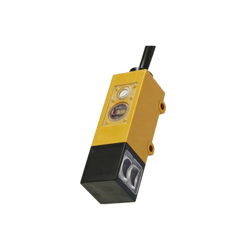
Retro-reflective photoelectric sensors, often simply called retro-reflective sensors, operate on a fundamental principle of light beam reflection. The sensor itself contains both a light emitter, typically an LED (Light Emitting Diode) or laser diode, and a light receiver (phototransistor or photodiode) housed within a single unit. The key component is a specialized reflector, known as a retro-reflector or corner-cube prism, placed opposite the sensor. This reflector is designed to return the emitted light beam directly back to its source along the same path, regardless of the angle of incidence within a specified range. The sensor's internal logic is tuned to detect the presence of this specific returned beam. When an opaque object interrupts the beam between the sensor and the reflector, the light path is broken, causing the receiver to detect a significant drop in light intensity. This state change triggers the sensor's output switch, signaling the object's presence.
Key Components and Their Functions
The effectiveness of a retro-reflective sensor hinges on its components. The light emitter must produce a consistent, modulated beam—often infrared, red visible, or laser light—to distinguish it from ambient light. Modulation involves pulsing the light at a high frequency, allowing the receiver's circuit to ignore constant background illumination. The retro-reflector itself is a critical element. Composed of many small, three-sided corner cubes, it reflects incoming light precisely back to its origin. This is superior to a standard mirror, which would reflect light at an angle equal to the incidence angle, potentially missing the receiver if not perfectly aligned. The receiver includes a lens and a filtering circuit tuned to the emitter's modulation frequency, ensuring high immunity to optical noise from factory lighting or sunlight.
Advantages Over Other Sensor Types
Compared to other photoelectric sensing modes, retro-reflective models offer distinct benefits. Versus through-beam (or opposed) sensors, which require separate emitter and receiver units, retro-reflective sensors simplify installation and wiring by needing only one electrical connection point and one reflector. This reduces cost and alignment complexity. Compared to diffuse (proximity) sensors, which detect light reflected directly off the target object, retro-reflective sensors have a much longer sensing range for a given size and power. They are also less sensitive to the target object's color, surface texture, or reflectivity, as they rely on the consistent, high-reflectivity signal from the dedicated reflector, not the object itself.
Common Industrial Applications
These sensors are ubiquitous in automation and packaging. A primary application is object detection on conveyors, such as verifying the presence of boxes, bottles, or parts at specific stations for counting, sorting, or triggering subsequent actions. They are ideal for detecting transparent objects like glass or plastic bottles, as specialized polarizing filters can be used. In this configuration, the sensor emits polarized light. The retro-reflector includes a de-polarizing element, but a smooth, transparent object will not depolarize the light, allowing the sensor to differentiate between the reflector's signal and a transparent object's reflection. They are also used for door and gate monitoring, pallet positioning, and in automated storage and retrieval systems for detecting the presence of totes or shelves.
Critical Selection Criteria
Choosing the correct sensor requires evaluating several parameters. Sensing range is paramount; it must comfortably exceed the actual working distance, with a 30-50% safety margin. The beam pattern (spot size) should be appropriate for the target size; a small, focused beam (often from a laser model) is needed for detecting small objects or precise edges. Environmental factors are crucial: sensors with high IP (Ingress Protection) ratings (e.g., IP67, IP69K) are necessary for washdown or dusty areas. The housing material (e.g., stainless steel for corrosive environments) and temperature rating must suit the operating conditions. Output type (PNP/NPN, analog, IO-Link) must match the control system. For challenging applications involving highly reflective backgrounds or detecting transparent materials, models with background suppression or polarization filters are essential.
Installation and Alignment Best Practices
Proper installation ensures reliable operation. Mount the sensor and reflector securely to prevent vibration-induced misalignment. The initial alignment process is straightforward: power the sensor and use its built-in alignment indicator (often an LED) while manually aiming it at the reflector. Fine-tune the position until the indicator shows maximum signal strength (steady light or specific blink pattern per the manual). Ensure the optical path is free of obstructions like dust, steam, or stray reflective surfaces that could cause false triggers. For long-range applications, ensure the reflector size is adequate, as a larger reflector area increases the effective returned signal strength. Regular maintenance, including lens cleaning, is recommended in dirty environments.
Troubleshooting Common Issues
Sensor malfunction often manifests as false triggers or failure to detect. First, verify power and wiring connections. Check the alignment; even slight shifts can break the beam path. Clean the sensor's lens and the reflector surface, as dirt, oil, or condensation can attenuate the light beam. Inspect for any new obstructions or highly reflective objects in or near the beam path. For intermittent problems, consider electrical noise; ensure cables are not run parallel to high-voltage lines and that grounding is proper. If detecting transparent objects, verify that the correct polarized filter model is being used and that the object is indeed breaking the beam adequately. Consulting the sensor's diagnostic indicators, if available, can pinpoint issues like marginal signal strength or overload.