Understanding the Core Components
In industrial automation and control systems, the synergy between a proximity switch sensor and an amplifier is fundamental. A proximity sensor, typically inductive or capacitive, detects the presence or absence of a metallic or non-metallic target without physical contact. It generates a small, raw electrical signal upon detection. However, this signal is often insufficient in strength or unsuitable in form for direct interface with higher-level control systems like PLCs (Programmable Logic Controllers) or motor drives. This is where the amplifier, also commonly referred to as a converter or interface module, plays its critical role. The amplifier conditions, amplifies, and converts the sensor's signal into a robust, standardized output, such as a solid-state relay (SSR) output, a voltage signal (0-10V), or a current signal (4-20mA), ensuring reliable and noise-immune communication within the control circuit.
Wiring Configurations and Standards
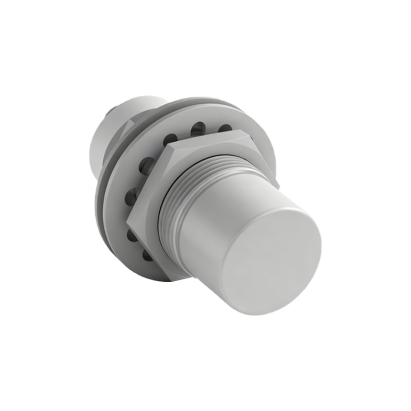
Correct wiring is paramount for system safety and functionality. Proximity sensors are generally available in three-wire (PNP or NPN) and two-wire (AC or DC) configurations. When connecting to an amplifier, matching the sensor type to the amplifier's input specifications is the first step. For a three-wire DC sensor, the brown wire is typically connected to the positive supply voltage (+V), the blue wire to the common negative (0V), and the black wire is the signal output, which feeds into the amplifier's input terminal. The amplifier itself requires a separate power supply, which must be compatible with its rated voltage (e.g., 12-24V DC or 90-250V AC). The output side of the amplifier is then wired to the load (e.g., a PLC input module, a relay coil, or a contactor). Adherence to color codes and terminal designations as per IEC 60947-5-2 or manufacturer datasheets is non-negotiable. Always implement proper cable shielding and grounding techniques to mitigate electromagnetic interference (EMI), especially in environments with heavy machinery or variable frequency drives.
Key Parameters for System Tuning
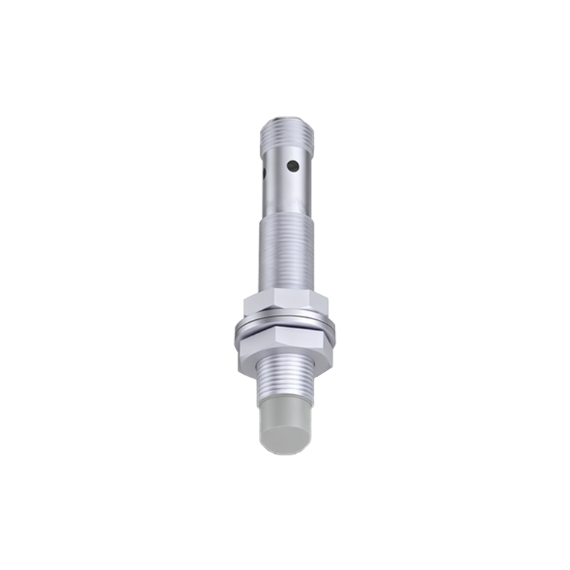
Simply connecting wires is not enough; optimal performance requires precise parameter adjustment on the amplifier. Key settings include the response time or switching frequency, which determines how quickly the amplifier reacts to the sensor's signal. Setting this too fast in a noisy environment can cause false triggering, while setting it too slow may miss rapid target movements. The hysteresis setting is crucial for preventing output chatter when a target is at the edge of the sensing range. Amplifiers often feature a sensitivity or gain adjustment potentiometer. This allows engineers to fine-tune the system's detection threshold, effectively extending or reducing the nominal sensing distance of the proximity switch to suit specific application needs, such as detecting small or poorly aligned targets.
Practical Application Scenarios
The combination of a proximity sensor and amplifier finds extensive use across various industries. In automotive assembly lines, an inductive proximity sensor detects a metal component on a conveyor. Its signal, amplified and converted to a 24V DC pulse, triggers a robotic arm for the next operation. In packaging machinery, a capacitive proximity sensor detects the level of liquid or powder inside a non-metallic container. The amplifier converts this signal into a stable 4-20mA analog output, which is fed into a process controller for precise level monitoring and control. Another critical application is in high-speed counting and positioning systems, where the fast response of the amplifier ensures accurate event counting or precise stopping position of a moving part.
Troubleshooting Common Issues
Even with correct installation, issues may arise. A frequent problem is no output signal. The first step is to verify power supply to both the sensor and the amplifier using a multimeter. Check for loose connections or damaged cables. If power is confirmed, use the amplifier's diagnostic LED indicators (usually for power, input status, and output status) to isolate the fault. If the input LED activates but the output does not, the issue may lie in the amplifier's internal settings or a faulty output stage. Intermittent operation often points to EMI or insufficient sensor sensing distance. Ensure proper shielding and consider increasing the sensor-to-target distance or adjusting the amplifier's sensitivity. Always consult the manufacturer's technical documentation for specific error codes and recommended corrective actions.
Selection Criteria and Best Practices
Selecting the right sensor-amplifier pair is critical for project success. Key selection factors include the sensing object material (metal, plastic, liquid), required sensing distance, environmental conditions