Introduction to Photoelectric Sensor Operation
Photoelectric sensors are fundamental components in industrial automation, providing non-contact detection of objects. They operate by emitting a beam of light, typically from an LED, and detecting changes in the received light signal. The three primary types are through-beam, retro-reflective, and diffuse reflective. Despite their reliability, various factors can lead to erroneous readings, causing production downtime, quality issues, or safety concerns. Understanding the root causes of these failures is critical for maintaining efficient and safe operations. This article delves into the most common reasons for photoelectric sensor errors and provides practical guidance for diagnosis and resolution.
Environmental Contamination and Lens Obstruction
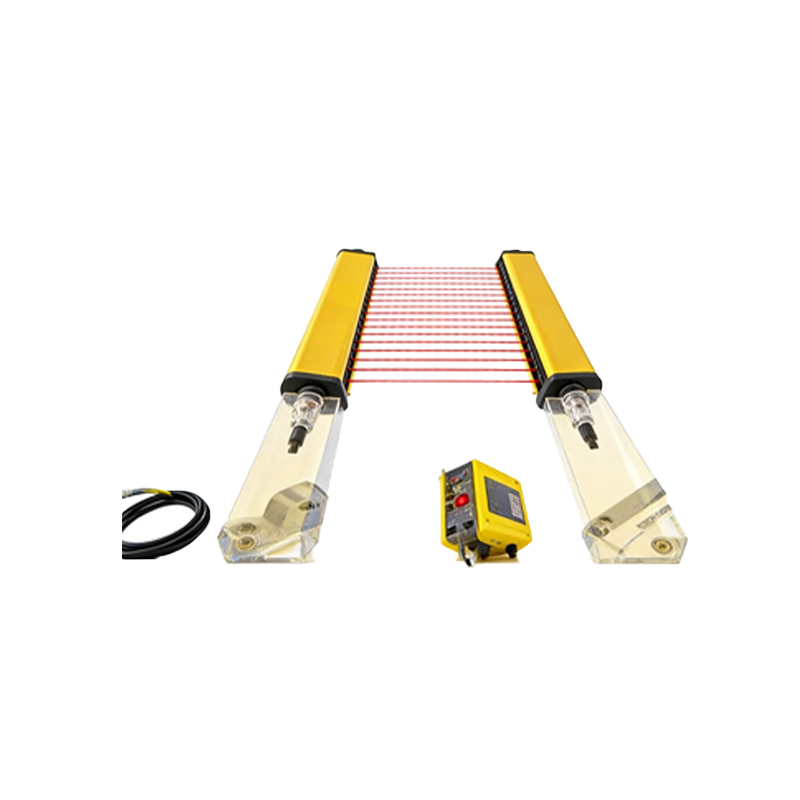
One of the most prevalent causes of sensor malfunction is environmental contamination. Dust, dirt, oil mist, coolant, or other airborne particles can accumulate on the sensor's lens or the reflector's surface. This buildup attenuates the emitted or received light signal. In diffuse sensors, it can cause false triggering by scattering light, making the sensor perceive an object when none is present. For through-beam and retro-reflective types, contamination can weaken the signal to a point below the detection threshold, leading to missed detections. Regular, scheduled cleaning using appropriate, non-abrasive materials is essential. In harsh environments, selecting sensors with higher IP ratings, protective air curtains, or specialized lens coatings can mitigate this issue significantly.
Incorrect Alignment and Mechanical Vibration
Precise optical alignment is paramount, especially for through-beam and retro-reflective sensors. Even minor misalignment, often caused by mechanical shock, thermal expansion of mounting structures, or improper initial setup, can drastically reduce signal strength. In through-beam systems, the receiver must be directly aligned with the emitter. For retro-reflective models, the sensor must be squarely aimed at the reflector. Mechanical vibration from nearby machinery can cause intermittent alignment shifts, resulting in flickering or unstable output. Securing mounts with locking nuts, using alignment tools provided by manufacturers, and installing sensors on stable, vibration-damped platforms are effective countermeasures. Periodic realignment checks should be part of routine maintenance.
Electrical Noise and Interference
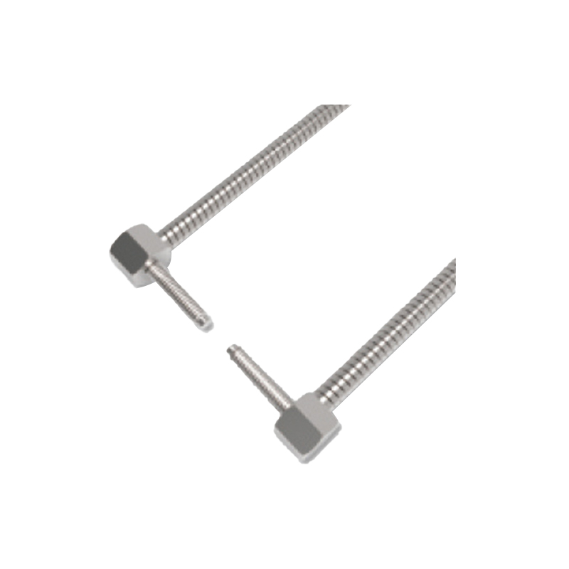
Industrial environments are rich sources of electromagnetic interference (EMI) and radio frequency interference (RFI). Noise can be induced into sensor cables or circuitry from sources like variable frequency drives (VFDs), welding equipment, large motors, or radio transmitters. This interference can cause erratic switching, false triggers, or even damage the sensor's internal electronics. To combat electrical noise, use shielded cables and ensure proper grounding practices by connecting the shield to ground at the controller end only. Physically separating sensor cables from power lines, using ferrite cores on cables, and selecting sensors with robust noise immunity specifications are highly recommended strategies. Employing DC sensors instead of AC models can also reduce susceptibility in some cases.
Inadequate Sensing Range and Object Characteristics
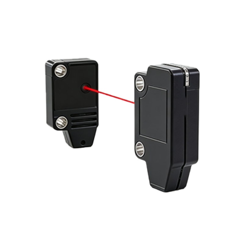
Operating a sensor beyond its specified sensing range is a common setup error. Every sensor has a defined operating distance, which can be affected by the target object's properties. For diffuse sensors, the detection range is highly dependent on the object's size, color, and surface texture. Dark, matte, or small objects absorb or scatter more light, reducing the effective range compared to light-colored, reflective, or large objects. Using a sensor with an insufficient excess gain for the application will lead to unreliable detection. Always refer to the sensor's data sheet for derating curves and ensure a sufficient margin of safety. For challenging objects, consider sensors with background suppression or true background suppression technology, which are less sensitive to color and surface finish.
Optical and Ambient Light Interference
Ambient light can be a significant source of error, particularly for sensors operating in the visible or near-infrared spectrum. Sunlight, factory lighting (especially strobe lights or LEDs), or light from other sensors can saturate the receiver, causing a constant "on" state, or create fluctuating signals. Through-beam sensors are generally more immune, but diffuse and retro-reflective types are vulnerable. Solutions include using sensors with modulated light (pulsed LED) and synchronous detection, which ignores constant ambient light. Selecting sensors with a different operating wavelength (e.g., green light for red object detection, or laser models for precision) can help. Physical shielding or hoods around the sensor head can also block extraneous light sources.
Power Supply Issues and Load Compatibility
Unstable or incorrect power supply voltage is a frequent but overlooked culprit. Voltage spikes, sags, or ripple can disrupt the sensor's internal circuitry. Operating a sensor below its minimum voltage can cause it to drop out, while excessive voltage can lead to permanent damage. Additionally, incompatibility with the load can cause errors. Exceeding the maximum switching current or inrush current rating of the sensor's output can damage the output transistor. Inductive loads (like solenoids or relays) require protective circuits such as flyback diodes to suppress voltage transients. Always ensure the power supply is properly sized, stable, and protected. Using a separate, regulated power supply for sensitive sensor networks is often a wise investment.
Sensor Deterioration and End-of-Life
Like all electronic components, photoelectric sensors have a finite operational lifespan. The LED light source gradually degrades over tens of thousands of hours, reducing its output intensity. This slow decline can eventually lead to a loss of sensing margin and intermittent failures. Environmental factors like extreme temperatures, humidity, and chemical exposure can accelerate the aging of lenses, housings, and electronic components. Implementing a predictive maintenance schedule that includes periodic performance checks—measuring signal strength or excess gain—can help identify sensors nearing end-of-life before they cause a production stoppage. Proactive replacement based on runtime or performance metrics is more efficient than reactive repair.
Systematic Troubleshooting Methodology
When an error occurs, a systematic approach is key. First, observe the symptom: is the sensor constantly on, constantly off, or flickering? Verify the basics: power connections, voltage, and fuse integrity. Use an indicator LED or a multimeter to check the output status. If possible, monitor the received light intensity or amplifier display if the sensor has one. Temporarily substitute a known-good sensor or test in a controlled environment to isolate the problem. Consult the manufacturer's manual for specific diagnostic modes or error codes. Documenting incidents and solutions creates a valuable knowledge base for future troubleshooting, reducing mean time to repair (MTTR) and improving overall system reliability.