Understanding Proximity Switch Fundamentals
Proximity switches, or proximity sensors, are non-contact electronic devices designed to detect the presence or absence of an object within a specified sensing range without physical contact. Their operation hinges on generating an electromagnetic field or a beam of radiation. When a target object enters this field, it causes a change in the field's state, which is then converted by the sensor's circuitry into a binary electrical signal—typically an ON/OFF output. This fundamental principle allows for reliable detection of metallic or, depending on the technology, non-metallic objects. The core advantage lies in their durability; with no moving parts to wear out from mechanical contact, they offer exceptionally long service life and high reliability in harsh industrial environments characterized by dust, moisture, and vibration. Common output types include NPN (sinking), PNP (sourcing), and two-wire AC/DC configurations, allowing for seamless integration into diverse control systems like PLCs (Programmable Logic Controllers).
Selecting the Core Sensing Technology
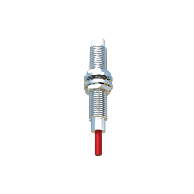
The choice of sensing technology is the most critical decision in the design phase, directly impacting performance, cost, and application suitability. The three primary types are inductive, capacitive, and photoelectric. Inductive proximity sensors are the most prevalent in industrial settings. They generate an oscillating electromagnetic field and detect the eddy current losses induced in conductive, typically metallic, targets. They are ideal for detecting metals like steel, aluminum, or copper but are ineffective for non-metals. Capacitive sensors, in contrast, can detect both metallic and non-metallic materials (plastics, wood, liquids, granules) by sensing changes in capacitance caused by the dielectric properties of the target entering an electrostatic field. Photoelectric sensors use a light beam (visible, infrared, or laser) and detect the presence of an object by either the interruption (through-beam) or reflection (retro-reflective, diffuse) of that beam, offering the longest sensing ranges and versatility for diverse materials and colors.
Key Electrical and Mechanical Design Parameters
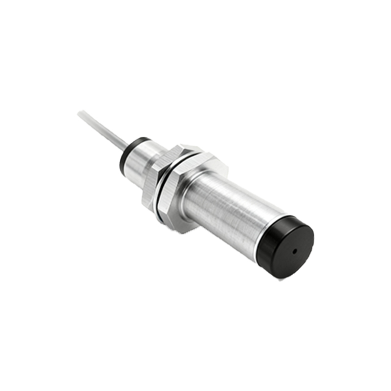
A robust design meticulously defines several key parameters. The sensing range, or nominal range (Sn), specifies the standard operating distance for which the sensor is calibrated. Designers must account for a safety factor, often derating the usable range to 70-80% of Sn to ensure reliability against target material variations and environmental factors. The housing material, typically nickel-plated brass, stainless steel, or PBT plastic, must be selected for chemical resistance and mechanical strength. The protection rating, denoted by IP (Ingress Protection) codes like IP67 or IP69K, is crucial for defining resistance to dust and water ingress. Electrically, the design must specify operating voltage ranges (e.g., 10-30V DC, 20-250V AC), current consumption, and output switching capacity. Incorporating reverse polarity protection, short-circuit protection, and overload protection circuits is essential for safeguarding the sensor and the connected control system from wiring errors and fault conditions.
Circuit Design and Signal Conditioning
The internal electronic circuitry is responsible for generating the sensing field, detecting minute changes, and providing a clean, stable output signal. An inductive sensor's core typically consists of an LC oscillator circuit, a demodulator, a Schmitt trigger, and an output amplifier. The oscillator creates the high-frequency field. When a metal target enters, it absorbs energy, causing the oscillation amplitude to dampen. This change is demodulated into a DC voltage level, which is then compared against a predefined threshold by the trigger circuit. Hysteresis is intentionally designed into the trigger to prevent output chattering when the target is at the exact sensing point. For digital outputs, the final stage uses a transistor (for DC sensors) or a triac/relay (for AC sensors) to switch the load. Advanced designs incorporate diagnostic LEDs, analog output options (4-20mA, 0-10V), and IO-Link digital communication for parameterization and data exchange.
Environmental Considerations and Robustness
Industrial sensors face extreme conditions. The design must ensure electromagnetic compatibility (EMC) to prevent malfunction from nearby motors, variable frequency drives (VFDs), or welding equipment. This involves shielding, filtering, and compliance with standards like IEC 60947-5-2. Temperature stability is another vital factor; components must be selected to operate across a wide range, commonly from -25°C to +70°C. For high-temperature applications near furnaces, specialized models are required. Resistance to mechanical shock and vibration is achieved through robust internal construction, potting critical circuits with epoxy resin, and secure mounting of components. For washdown environments in food and beverage industries, sensors with polished stainless steel housings and high IP69K ratings are necessary to