Understanding Proximity Angle Sensor Fundamentals
Proximity angle sensors, often rotary or angular position sensors, are critical components in modern industrial automation and motion control systems. They detect the angular position or rotational movement of a shaft, rotor, or other rotating element without physical contact, typically using inductive, magnetic, or capacitive sensing principles. The core function is to provide precise, real-time feedback on angular displacement, which is essential for closed-loop control in machinery such as robotic arms, CNC machines, conveyor systems, and automotive steering applications. A proper wiring connection is paramount to ensure accurate signal transmission, system safety, and sensor longevity. Incorrect wiring can lead to erroneous readings, sensor damage, or complete system failure.
Key Components and Terminal Identification
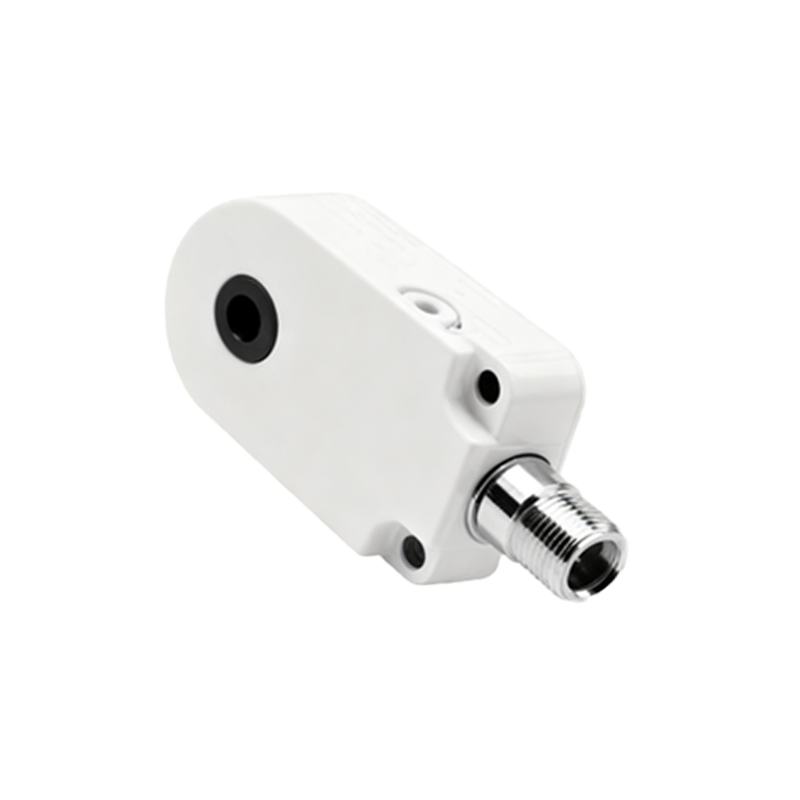
Before examining the wiring diagram, it is crucial to identify the standard terminals found on most industrial proximity angle sensors. While models vary by manufacturer (e.g., Pepperl+Fuchs, Sick, Omron), common terminal designations include: Supply Voltage (Vcc or +Vs), Ground (GND or 0V), and Output Signal. The output type defines the wiring specifics. Common outputs are Analog Voltage (e.g., 0-10V), Analog Current (e.g., 4-20mA), and digital signals like Push-Pull, NPN (sinking), or PNP (sourcing). Many sensors also feature terminals for shielding and diagnostic LEDs. The sensor's datasheet is the ultimate authority for terminal labels and functions. Always de-energize the control circuit before handling any connections.
Standard Wiring Diagram for a 3-Wire DC Sensor
The 3-wire DC sensor is the most prevalent configuration. Consider a sensor with a PNP (sourcing) output. The wiring diagram involves three core connections. First, connect the Brown wire (typically) or the terminal marked +V to the positive DC supply voltage, often 10-30V DC. Second, connect the Blue wire or terminal marked 0V to the power supply ground. This provides operating power to the sensor's internal electronics. Third, the Black wire (or terminal marked OUT) is the switched output. This wire carries the signal to the load, which is usually a programmable logic controller (PLC) input, a relay, or an indicator. The load is then connected back to the power supply ground, completing the circuit. For an NPN (sinking) sensor, the output logic is reversed; the Black wire connects to the load, and the other side of the load connects to the positive supply.
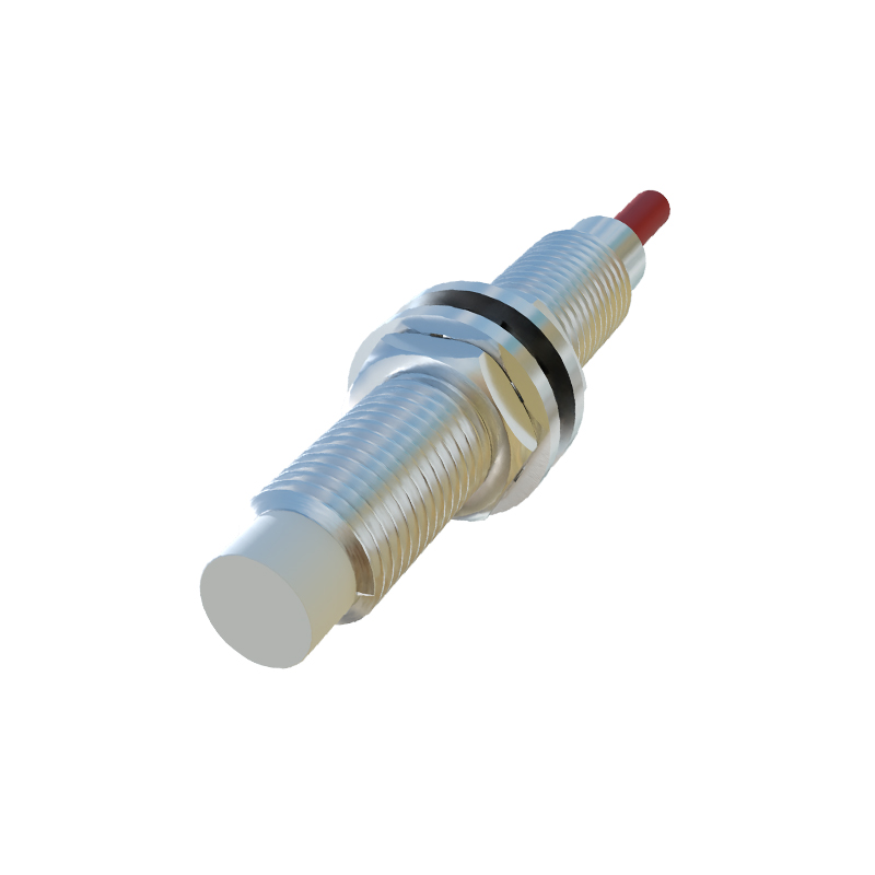
Wiring for Analog Output Sensors
Analog output sensors, providing a continuous voltage or current proportional to the measured angle, require careful wiring to avoid signal noise. A typical 4-wire analog voltage sensor (0-10V) will have: Brown (+Vs), Blue (0V), Black (Signal Output), and a White or Shield wire. The supply wires (Brown, Blue) power the sensor. The Black wire carries the analog signal to the measurement device's analog input card. The shield wire must be connected to a clean earth ground at one end only (usually at the controller side) to prevent ground loops. For 4-20mA two-wire loop-powered sensors, wiring is different; the sensor is connected in series with the power supply and the receiving device, using only two wires that carry both power and the signal.
Shielding, Grounding, and Noise Mitigation
Industrial environments are rich in electromagnetic interference (EMI) from motors, drives, and switching equipment. Proper shielding and grounding are non-negotiable for signal integrity. Always use shielded, twisted-pair cables for sensor connections. The cable shield, often a braided copper layer, should be connected to the functional earth (FE) or ground terminal on the sensor housing (if present) and securely grounded at the control panel entry point via a cable gland with shield clamp. Avoid grounding both ends of the shield, which can create a ground loop. Maintain separation between sensor signal cables and high-voltage power lines; cross them at 90-degree angles if they must intersect.
Integration with PLCs and Controllers
Integrating the sensor with a PLC is a common final step. For a digital PNP sensor, the Black output wire connects to a specific digital input (DI) point on the PLC. The PLC's DI common terminal (often labeled M or COM) is connected to the 0V of the same power supply. This configuration allows the sensor to "source" current into the PLC input. For analog sensors, the signal wire connects to an analog input module channel. Ensure the analog input's configuration (voltage or current, range) matches the