Introduction to Photoelectric Sensor Principles
Photoelectric sensors operate by converting light signals into electrical signals through photoelectric effects. These devices typically consist of an emitter, which projects light, and a receiver, which detects changes in the light beam. The core principle involves modulating light intensity, which is then interrupted or reflected by a target object. This alteration in light conditions generates a corresponding electrical signal in the receiver circuit. Common types include through-beam, retro-reflective, and diffuse reflection sensors, each suited for specific detection scenarios. The choice of sensor type directly impacts circuit design parameters such as sensitivity, response time, and noise immunity. Understanding these fundamentals is essential for designing robust signal detection circuits that perform reliably in industrial environments.
Circuit Components and Signal Processing
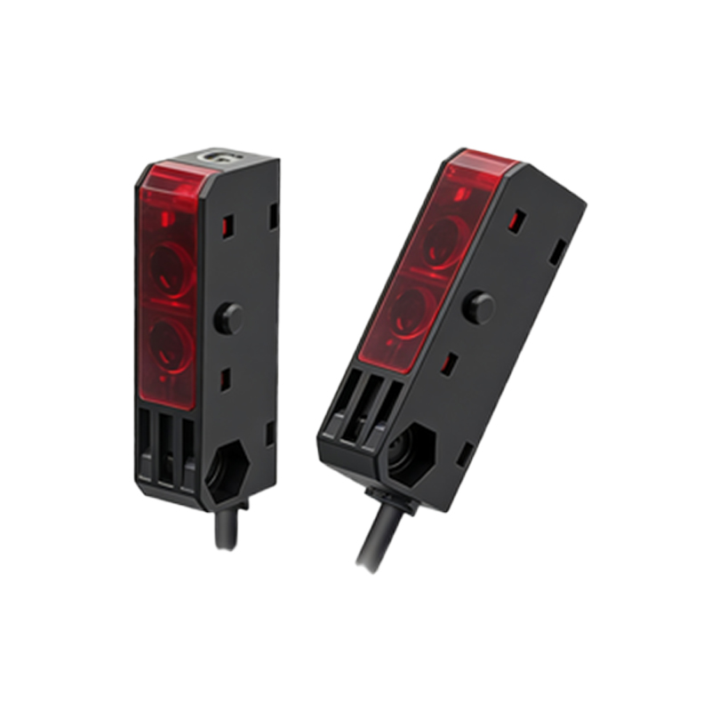
A typical photoelectric sensor circuit comprises several key components: the photodetector (e.g., phototransistor or photodiode), amplification stages, filtering elements, and output interfaces. The photodetector converts incident light into a weak current signal, which is then amplified using operational amplifiers or transistor-based circuits. Signal conditioning often involves low-pass filters to eliminate high-frequency noise from ambient light sources or electromagnetic interference. Additionally, voltage comparators are employed to convert analog signals into digital outputs, enabling compatibility with microcontrollers or PLCs. Proper selection of components, such as choosing photodetectors with appropriate spectral response and amplifiers with low offset voltage, ensures accurate signal detection even in challenging conditions like varying ambient light.
Design Considerations for Industrial Applications
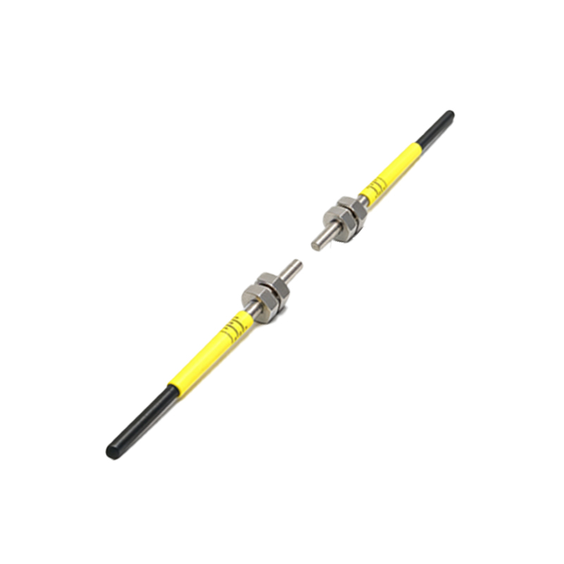
Industrial environments impose stringent requirements on photoelectric sensor circuits, including durability, stability, and resistance to environmental factors. Designers must account for factors such as temperature fluctuations, humidity, and mechanical vibrations. For instance, temperature compensation circuits may be integrated to maintain consistent performance across operating ranges. Shielding and grounding techniques are critical to minimize electromagnetic interference from nearby machinery. Furthermore, circuits should incorporate overload protection to prevent damage from voltage spikes or short circuits. The use of modular designs facilitates maintenance and replacement, reducing downtime in production lines. By addressing these considerations, engineers can develop circuits that deliver long-term reliability in harsh industrial settings.
Noise Reduction and Signal Integrity
Maintaining signal integrity is paramount in photoelectric sensor circuits, as noise can lead to false triggers or missed detections. Common noise sources include ambient light (e.g., sunlight or fluorescent lamps), electrical noise from power supplies, and crosstalk between multiple sensors. To mitigate these issues, designers implement strategies such as optical filtering—using lenses or coatings that match the emitter's wavelength—and synchronous detection techniques, where the emitter is pulsed at a specific frequency. Electrical filtering, such as RC networks or active filters, helps suppress high-frequency noise. Additionally, proper PCB layout practices, like separating analog and digital grounds and minimizing trace lengths, enhance signal clarity. These measures collectively ensure accurate detection even in noisy industrial environments.
Integration with Control Systems
Photoelectric sensor circuits often interface with broader control systems, such as programmable logic controllers (PLCs) or industrial computers. The output stage of the circuit must provide compatible signals, typically in the form of digital switches (e.g., NPN or PNP transistors) or analog voltage/current outputs (e.g., 0-10V or 4-20mA). For digital interfaces, circuits include output drivers capable of sinking or sourcing sufficient current for PLC input modules. In analog systems, precision voltage regulators and current loops ensure linear signal transmission over long distances. Communication protocols like IO-Link are increasingly integrated for advanced diagnostics and parameter configuration. Seamless integration enables real-time monitoring and control, enhancing automation efficiency in applications like conveyor systems or robotic assembly lines.
Future Trends and Innovations
Advancements in photoelectric sensor technology continue to drive circuit design innovations. Emerging trends include the adoption of smart sensors with embedded microprocessors for self-calibration and fault detection. Miniaturization allows for compact circuits suitable for space-constrained applications, while energy-efficient designs support battery-operated devices in IoT systems. Enhanced materials, such as silicon carbide photodetectors, offer improved performance in high-temperature environments. Additionally, the integration of machine learning algorithms enables adaptive threshold adjustment based on environmental changes. These developments promise higher precision, reduced maintenance, and greater flexibility, positioning photoelectric sensors as key components in next-generation industrial automation and smart manufacturing initiatives.