Introduction to 2-Wire Normally Open Proximity Sensors
In the realm of industrial automation and control systems, proximity sensors are indispensable components for non-contact object detection. Among the various configurations available, the 2-wire normally open (NO) proximity sensor stands out for its simplicity and direct integration into control circuits. Unlike their 3-wire counterparts, which require separate power, signal, and ground connections, 2-wire sensors are wired in series with the load, typically a programmable logic controller (PLC) input or a relay coil. This design inherently provides a normally open contact that closes upon detecting a target within its sensing range. The fundamental operating principle involves the sensor acting as a variable resistor or switch. When no target is present, the internal switching element remains open, preventing current flow. Upon target detection, the switch closes, allowing current to pass through the sensor to power the load, thus signaling the target's presence.
Core Operating Principles and Electrical Characteristics
The operation of a 2-wire normally open DC sensor is analogous to a switch. It must have a minimum operating current, known as the "minimum load current," to remain active and a maximum current it can safely switch, termed the "maximum switching current." A critical parameter is the residual current or leakage current. When in the "off" state (no target), a small leakage current, typically in the microampere range, still flows through the sensor. This current must be lower than the "off-state current" requirement of the connected load (e.g., the PLC input module) to prevent false triggering. Conversely, when activated, the sensor exhibits a voltage drop across its terminals, known as the "on-state voltage drop." This drop, usually between 1.5 to 3 volts for DC sensors, reduces the voltage available to the load and must be accounted for in system design to ensure the load receives sufficient voltage to operate reliably.
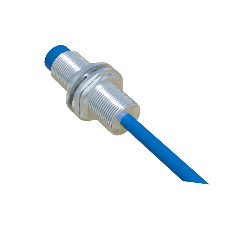
Key Advantages in Industrial Applications
The primary advantage of the 2-wire NO configuration is its wiring simplicity, which translates to reduced installation time, lower material costs, and less space required in cable ducts and control cabinets. This makes them particularly advantageous in applications with a high number of sensor points. Their inherent short-circuit protection, as they are connected in series with the load, is another significant benefit. Furthermore, they offer easy replacement of mechanical limit switches, providing a solid-state, maintenance-free solution with a longer operational lifespan. The normally open function is intuitive for control logic; the circuit is completed only when an object is detected, which is a straightforward concept for designing safety interlocks or part-present verification systems in assembly and packaging machinery.
Critical Considerations for System Design
Successful implementation requires careful attention to several factors. First, the leakage current must be compatible with the connected load's specifications. Using a load resistor (bleeder resistor) in parallel with the PLC input is a common practice to ensure the leakage current bypasses the sensitive input circuitry. Second, the voltage drop of the sensor must be subtracted from the supply voltage to verify the load receives adequate voltage. For instance, with a 24VDC supply and a sensor drop of 2.5V, the load sees 21.5V. Designers must also consider the sensor's switching frequency or response time, especially in high-speed applications. Additionally, the choice between AC and DC versions is crucial; DC 2-wire sensors are more common and avoid issues with zero-crossing found in AC types. Proper shielding and grounding are essential in electrically noisy environments to prevent electromagnetic interference from causing erratic behavior.
Installation and Wiring Best Practices
Correct installation is paramount for reliable operation. Always refer to the manufacturer's datasheet for specific wiring diagrams and specifications. For a standard DC 2-wire NO sensor, one wire is connected to the positive supply voltage, and the other wire is connected to the load, which then returns to the negative side of the supply. It is vital to observe polarity for DC sensors. Sensors should be mounted securely to minimize vibration, and the sensing face must be positioned with the correct gap from the target material as specified. Avoid mounting metallic sensors face-to-face without sufficient lateral separation to prevent mutual interference. When wiring, use twisted-pair cables for DC sensors to reduce noise pickup and ensure all connections are tight and corrosion-free. Always perform a functional test under normal operating conditions after installation.
Troubleshooting Common Operational Issues
Common issues with 2-wire NO sensors often stem from electrical mismatches. If a sensor fails to trigger the load, check for insufficient voltage at the load due to a high on-state voltage drop or an underrated power supply. Measure the voltage across