Introduction to Through-Beam Photoelectric Sensors
Through-beam photoelectric sensors, also known as opposed-mode sensors, are widely used in industrial automation for object detection, counting, and positioning. These sensors consist of two separate units: a transmitter (emitter) and a receiver. The transmitter emits a beam of light, typically infrared or visible, which is received by the receiver. When an object interrupts this beam, the sensor triggers an output signal. This design offers high reliability and long sensing ranges, making it ideal for harsh environments with dust, dirt, or vibration. The key to optimizing their performance lies in understanding the parameters labeled on the sensor, particularly "L" and "D," which are critical for installation and operation.
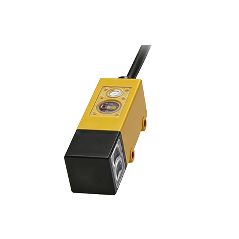
Meaning of L: Sensing Distance or Range
In through-beam photoelectric sensors, "L" stands for the sensing distance or range, often referred to as the "operating distance" or "detection range." This parameter indicates the maximum distance between the transmitter and receiver at which the sensor can reliably detect an object interrupting the beam. It is typically measured in meters or feet, depending on regional standards. The value of L is determined by factors such as the light source intensity, lens design, and environmental conditions. For instance, a sensor with L=10m can effectively operate when the transmitter and receiver are placed up to 10 meters apart. Exceeding this distance may lead to unstable detection due to signal attenuation. Engineers must consider L during system design to ensure proper spacing and avoid false triggers, especially in applications like conveyor systems or safety barriers.
Meaning of D: Beam Diameter or Spot Size
The letter "D" on through-beam photoelectric sensors denotes the beam diameter or spot size at a specific distance, usually at the receiver end. This parameter represents the width of the light beam as it reaches the receiver, affecting the sensor's resolution and accuracy. A smaller D allows for detecting tiny objects or precise edges, while a larger D provides tolerance for misalignment and environmental interference. For example, if D=50mm at L=5m, the beam spreads to 50mm in diameter when traveling 5 meters. This information is crucial for aligning the transmitter and receiver, as misalignment beyond D can cause signal loss. In practice, D helps in selecting sensors for applications requiring high precision, such as part inspection or robotic guidance, where even minor beam deviations matter.
Relationship Between L and D in Sensor Performance
L and D are interrelated parameters that influence the overall performance of through-beam photoelectric sensors. Generally, as L increases, D tends to expand due to beam divergence, which is the natural spreading of light over distance. This relationship is often specified in sensor datasheets with graphs or formulas. For instance, a sensor might have L=20m with D=100mm, meaning the beam width grows to 100mm at the maximum range. Understanding this correlation helps in optimizing detection scenarios: a longer L with a larger D may suit bulk material detection, while a shorter L with a smaller D is better for fine object sensing. Engineers should balance these factors based on application needs, considering trade-offs like alignment ease versus detection precision. Ignoring the L-D dynamic can lead to installation errors or reduced sensor lifespan.
Practical Applications and Selection Tips
In real-world industrial settings, through-beam photoelectric sensors with clear L and D specifications are used in diverse applications. For example, in packaging lines, sensors with L=15m and D=80mm can detect large boxes on fast conveyors, while in electronics assembly, L=2m and D=10mm sensors identify small components. When selecting a sensor, always check the datasheet for L and D values under standard conditions (e.g., clean air, ambient light). Consider environmental factors like fog or dust, which may reduce effective L and alter D. For alignment, use tools like alignment indicators or laser pointers, ensuring the beam stays within D at the receiver. Regular maintenance, such as lens cleaning, also preserves L and D accuracy over time, enhancing system reliability.
Common Misconceptions and Troubleshooting
A frequent misconception is that L and D are fixed regardless of environment, but they can vary with temperature, humidity, or obstructions. For instance, high temperatures might shorten L by affecting the light source. Troubleshooting issues often involves verifying L and D: if a sensor fails to detect objects, measure the actual distance and beam alignment against specifications. Use a multimeter or oscilloscope to check signal strength, which correlates with L performance. For D-related problems, like false triggers from nearby objects, ensure the beam is narrowly focused and shielded from stray light. Consulting manufacturer guidelines for L and D adjustments, such as sensitivity settings, can resolve many operational challenges without replacing hardware.
Conclusion and Industry Insights
Mastering the meanings of L and D on through-beam photoelectric sensors is essential for engineers in the electrical and automation fields. These parameters directly impact installation, performance, and maintenance, contributing to efficient and safe industrial operations. As technology advances, sensors with adjustable L and D features are emerging, offering greater flexibility. Always prioritize quality datasheets and real-world testing to validate specifications. By leveraging this knowledge, professionals can optimize sensor networks, reduce downtime, and adapt to evolving automation demands, ensuring robust solutions in sectors from manufacturing to logistics.