Understanding U-Shaped Photoelectric Sensors
U-shaped photoelectric sensors, also known as through-beam sensors, consist of two separate components: an emitter and a receiver. These components are positioned opposite each other within a U-shaped housing, forming a precise optical axis. The emitter continuously projects a light beam—typically infrared or visible red light—across the gap toward the receiver. When an object interrupts this beam, the receiver detects the absence or reduction of light, triggering a change in the sensor's output state. This fundamental operating principle is critical for applications requiring high-precision detection, such as object counting, edge guiding, or break detection in automated machinery. The robust U-shaped design provides inherent alignment stability, protecting the optical path from misalignment due to vibration or environmental factors, which is a key advantage over separate emitter-receiver setups.
Defining Normally Open and Normally Closed Contacts
In the context of sensor outputs, the terms Normally Open (NO) and Normally Closed (NC) refer to the electrical state of the sensor's output contacts under a condition where no object is present to interrupt the light beam—this is considered the "normal" state. For a U-shaped photoelectric sensor, the "normal" state is typically defined as the beam being uninterrupted. A Normally Open (NO) output means that when the light beam is intact (no object detected), the output circuit is open, and no current flows. When an object blocks the beam, the output circuit closes, allowing current to flow. Conversely, a Normally Closed (NC) output means the output circuit is closed and conducting current when the beam is uninterrupted. When an object blocks the beam, the circuit opens, stopping the current flow. This logical function is fundamental for integrating the sensor into control systems for safety interlocks, process sequencing, or alarm triggering.
Identifying the Output Configuration via Labeling
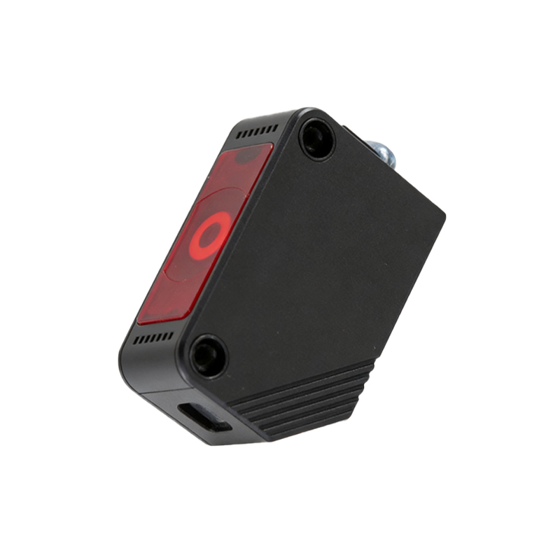
Manufacturers clearly indicate the output configuration on the sensor's housing or in its datasheet. The most direct method is to examine the product label or nameplate. Look for abbreviations such as "NO," "NC," or sometimes "N.O./N.C." if the sensor features a selectable output. Additionally, technical markings near the output terminals often use symbols: a diagram showing an open switch typically represents NO, while a closed switch represents NC. The model number itself may also contain codes indicating the output type; for instance, a suffix like "-NO" or "-NC" is common. It is imperative to consult the official product documentation, as terminology can vary slightly between brands. Never assume the function based solely on the physical appearance of the sensor.
Practical Testing Method with a Multimeter
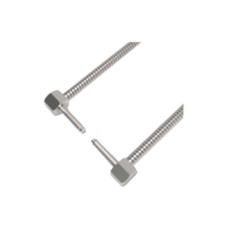
A hands-on method to determine the state involves using a digital multimeter. First, ensure the sensor is powered according to its specifications (e.g., 12-24V DC). Set the multimeter to measure resistance (Ohms) or continuity. For a three-wire sensor (brown: +V, blue: 0V, black: output), disconnect the black output wire from the control system. Place the multimeter probes between the black output wire and the blue (0V) wire. With no object in the U-gap (beam uninterrupted), observe the reading. A high resistance or no continuity indicates a Normally Open (NO) output. A low resistance or a continuity beep indicates a Normally Closed (NC) output. Then, insert an opaque object to block the beam. The state should reverse: an NO circuit will show continuity, and an NC circuit will show open. This test provides definitive, real-world verification.
Wiring Diagram and Schematic Interpretation
Analyzing the sensor's wiring diagram is a reliable engineering approach. The schematic symbol for the output is a switch. In a standard diagram for a DC PNP sensor (sourcing), the output switch is drawn between the output terminal and the positive supply. If the switch symbol is shown as open in its normal state (beam clear), it signifies a Normally Open logic. If it is shown as closed, it signifies Normally Closed. For NPN (sinking) sensors, the switch is between the output and negative. Diagrams for sensors with both NO and NC outputs will show two separate switch symbols, often labeled accordingly. Understanding these schematics is crucial for correctly integrating the sensor into programmable logic controller (PLC) input modules or relay circuits to achieve the desired machine logic.
Role of Output Logic in Control System Design
The choice between NO and NC is not arbitrary but a core part of control system design and safety. A Normally Closed configuration is often employed in safety-critical applications, such as a machine guard interlock. Here, the sensor's beam monitors the guard's position. If the guard is closed (beam intact), the NC circuit is closed, allowing the machine to operate. If the guard is opened (beam broken), the circuit opens, creating a fail-safe stop condition. This design ensures that a wire break or power loss to the sensor also results in a safe stop, mimicking a broken beam. Conversely, an NO configuration might be used for standard object detection where an active high signal upon detection is required for the process sequence. The selection directly impacts the ladder logic or control code, as the input instruction (e.g., XIC or XIO in PLCs) must match the sensor's physical behavior.
Configurable and Dual-Output Sensor Options
Many modern U-shaped photoelectric sensors offer configurable or dual outputs to increase application flexibility. Configurable sensors may have a physical switch or teach-in button to toggle the output logic between NO and NC. Dual-output sensors provide two separate physical output wires—one for NO and one for NC—allowing a single sensor to send two complementary signals to different parts of a control system. When dealing with such sensors, the determination of state is a matter of which output wire is connected. The datasheet will specify the wiring color code, typically black for NO and white for NC, or similar. This feature eliminates the need for external relays to invert signals and provides design engineers with greater versatility in creating control logic.