Introduction to Photoelectric Sensing
A photoelectric sensor is a device that uses light to detect the presence, absence, or distance of an object. Its fundamental principle is elegantly simple: a light emitter sends out a beam, and a receiver detects changes in this beam caused by a target object. This basic interaction forms the core of countless automation, safety, and detection applications. For engineers and hobbyists entering the field, understanding and building a simple version demystifies the technology and provides a solid foundation for more complex designs. The simplest design typically involves a modulated infrared LED as the emitter and a phototransistor as the receiver, creating a basic "opposed" or "through-beam" sensor.
Core Components and Selection
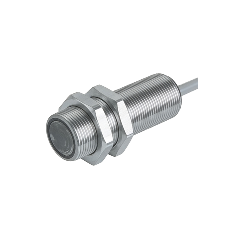
The minimalist design requires only a handful of key electronic components. First, the light source: an Infrared (IR) Light Emitting Diode (LED) is preferred for its immunity to ambient visible light interference. A standard 5mm IR LED with a wavelength of 940nm is common and cost-effective. For the receiver, a matching phototransistor is ideal. It acts like a switch whose conductivity is proportional to the amount of IR light hitting its base. You will also need current-limiting resistors for both the emitter and receiver legs. A 220-ohm resistor in series with the IR LED typically works well with a 5V supply. A 10k-ohm pull-up resistor is commonly used with the phototransistor in a voltage divider configuration to produce a clear digital signal.
Basic Circuit Design and Operation
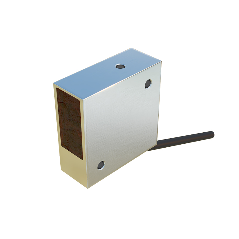
The circuit can be assembled on a breadboard for prototyping. Connect the anode of the IR LED to the 5V supply through the 220-ohm resistor, and its cathode to ground. For the phototransistor, connect its collector to the 5V supply via the 10k-ohm resistor. The emitter pin connects directly to ground. The output signal is taken from the junction between the phototransistor's collector and the 10k-ohm resistor. When no object interrupts the IR beam, light falls on the phototransistor, causing it to conduct. This pulls the output voltage at the junction low (near 0V). When an object blocks the beam, the phototransistor stops conducting, and the output is pulled high (to 5V) by the resistor. This provides a clean, binary signal.
Overcoming Ambient Light Challenges
A critical flaw in the ultra-simple DC-operated circuit is its susceptibility to ambient light, including sunlight or artificial room lighting, which can falsely trigger the phototransistor. The professional solution is modulation. This involves pulsing the IR LED at a specific high frequency (e.g., 1-10 kHz) using a simple 555 timer IC or a microcontroller pin. The receiver circuit is then coupled with a matching tuned filter or is designed to only respond to that specific frequency. This makes the sensor virtually immune to steady or slowly changing ambient light, as the receiver ignores any light signal not pulsing at the designated carrier frequency.
Implementing a Modulated Design
To upgrade the basic design, integrate a 555 timer configured in astable mode to pulse the IR LED. The timing resistors and capacitor set the desired frequency. The receiver side requires a bit more sophistication. The signal from the phototransistor is fed into an active band-pass filter or a dedicated IC like a 567 tone decoder tuned to the same frequency. Alternatively, a microcontroller can both generate the pulsed output and, on a separate input pin, sample the receiver's signal, using software to detect the presence of the specific pulse train. This modulated through-beam sensor is robust enough for most indoor industrial and hobbyist applications.
Alignment and Mechanical Considerations
The physical setup is as crucial as the circuit. For a through-beam sensor, the emitter and receiver must be precisely aligned on opposite sides of the detection path. Mounting them in small tubes or housings helps collimate the beam and shields the receiver from stray light. Ensuring a stable mechanical mounting prevents vibration from breaking alignment. The distance between emitter and receiver depends on the LED's power and the phototransistor's sensitivity; for simple components, a range of 10-50 cm is typical. For reflective sensing, both elements are placed side-by-side, facing the target, which simplifies mounting but is more susceptible to the target's color and reflectivity.
Testing and Calibration Procedure
After assembly, power the circuit and use a digital multimeter or an oscilloscope to monitor the output voltage. First, test the receiver's response by pointing a TV remote control at the phototransistor and pressing a button; the meter should flicker, confirming the component works. Then, align the emitter and receiver. With a clear path, the output should read low. Interrupt the beam with an opaque object; the output should switch high. For modulated designs, an oscilloscope is invaluable to verify the carrier frequency on the emitter and the clean, filtered signal on the receiver output. Adjust resistor values slightly if the output logic levels are not distinct enough.
Practical Applications and Next Steps
This simple sensor can immediately be used in projects like object counting on a conveyor, a break-in alarm beam, or a touchless toggle switch. Its output can directly drive an LED indicator, a buzzer, or feed into a microcontroller's digital input pin for further processing. From this foundational design, engineers can explore more advanced configurations: retro-reflective sensors using a mirror, diffuse sensors with angled optics, or analog sensors for distance measurement. Adding a comparator IC like an LM393 can provide adjustable sensitivity via a potentiometer. Mastering this simple photoelectric sensor design unlocks the door to a vast world of optical sensing and automation.