Introduction to Proximity Capacitive Sensing
Proximity capacitive sensors are fundamental components in modern industrial automation and control systems. Unlike mechanical switches or other sensing technologies, these devices operate without physical contact, detecting the presence or absence of a target object based on changes in capacitance. The core principle hinges on the ability to measure the capacitance between the sensor's active surface and the surrounding environment. When a target object enters the sensor's detection field, it alters the dielectric properties or the conductive area, leading to a measurable change in capacitance. This change is processed by the sensor's internal oscillator and evaluation circuitry, triggering a switching output. The technology is prized for its ability to detect a wide range of materials, including metals, plastics, glass, wood, and liquids, making it exceptionally versatile for diverse applications from packaging and material handling to level detection and touch interfaces.
The Fundamental Capacitance Model
At its heart, a capacitive proximity sensor functions as one plate of a capacitor, with the target object (or a grounded plane) acting as the other plate. The air gap and any material between them serve as the dielectric. The capacitance (C) is determined by the formula C = ε₀εᵣA/d, where ε₀ is the permittivity of free space, εᵣ is the relative permittivity (dielectric constant) of the material between the plates, A is the effective area of the plates, and d is the distance between them. In a typical sensing scenario, the sensor's active face and internal circuitry form one electrode. As a target approaches, it effectively increases the plate area (A) or changes the dielectric constant (εᵣ) in the field, thereby increasing the capacitance. The sensor is designed to be sensitive to these specific changes while compensating for or ignoring background environmental variations like humidity or temperature.
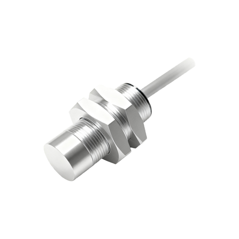
Internal Circuitry and Oscillation Principle
The practical implementation of this principle involves a high-frequency oscillator circuit connected to the active sensing electrode, often forming a capacitor in an RC or LC tank circuit. Under no-target conditions, the oscillator runs at a specific amplitude or frequency. When a detectable object enters the field, the increased capacitance alters the circuit's characteristics. This typically causes a change in the oscillation amplitude. A threshold detector circuit continuously monitors this amplitude. Once the change exceeds a pre-set threshold—corresponding to the configured sensing distance—the sensor's output state switches. More advanced sensors use frequency modulation or phase-locked loop techniques for greater stability and precision, filtering out noise and providing consistent performance even with varying target materials or environmental conditions.
Key Design Characteristics and Modes of Operation
Capacitive proximity sensors are designed with specific operational modes. The two primary modes are the dielectric sensing mode and the conductive sensing mode. In dielectric mode, the sensor detects non-conductive materials by sensing the increase in the dielectric constant (εᵣ) of the space between the electrodes. For instance, plastic or glass has a higher εᵣ than air, causing a detectable capacitance rise. In conductive mode, the target itself (like a metal or a conductive liquid) becomes the second electrode, dramatically increasing the capacitance. Design characteristics such as the sensor face geometry, shielding type, and housing material are critical. Shielded (flush-mountable) sensors have a focused field directly in front, ideal for flush installation in metal. Non-shielded sensors have a larger, more extended field, suitable for detecting materials with lower dielectric constants.
Compensation and Environmental Considerations
A significant challenge for capacitive sensors is their inherent sensitivity to environmental factors. Changes in ambient humidity, temperature, or the accumulation of dust and condensation on the sensor face can cause false triggering. To mitigate this, engineers incorporate compensation electrodes and sophisticated circuitry. A common method is to use a guard ring or a separate compensation electrode surrounding the main active electrode. This guard electrode is driven at the same potential as the sensing electrode, effectively containing the electric field and making the sensor insensitive to material adhering to the face. Additionally, temperature compensation circuits and adaptive threshold algorithms are employed to ensure stable switching points over the sensor's operational range, maintaining reliability in harsh industrial environments.
Application Examples in Industry
The versatility of capacitive sensors leads to widespread use. A classic application is level detection in tanks or silos for both liquids and granular solids. They can detect the presence of material through non-metallic container walls. In packaging, they verify the presence of a product in a bottle or a cap on a container, regardless of the material's color or transparency. On assembly lines, they count non-metallic parts like plastic components or cardboard boxes. They are also integral to human-machine interfaces (HMIs) as touch-sensitive buttons or