Understanding Photoelectric Sensor Basics
Photoelectric sensors are fundamental components in industrial automation, utilizing light beams to detect the presence, absence, or distance of objects. These sensors operate by emitting a light signal—typically infrared, visible red, or laser—from a transmitter. A receiver then detects changes in this light beam caused by an object interrupting or reflecting it. The core function is to convert this optical detection into an electrical output signal. This output is a discrete on/off signal, often referred to as a digital signal, which indicates the detection state. Understanding this basic principle of converting light into an electrical control signal is the first step in determining the correct connection point within a larger control system. The sensor itself is merely the detection device; its true purpose is realized only when its output is properly integrated to trigger an action in another machine or process.
Primary Connection Points: PLC Input Modules
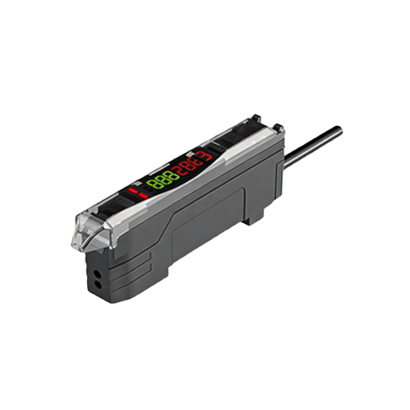
The most common destination for a photoelectric sensor's output wire is an input module on a Programmable Logic Controller (PLC). In standard wiring configurations, the sensor's output (often a black wire in a 3-wire DC sensor) is connected to a specific terminal on a PLC's digital input card. The sensor and the PLC input must share a common voltage reference, typically 24V DC in industrial settings. When the sensor detects an object, it switches its internal transistor, allowing current to flow from the voltage supply, through the sensor, into the PLC input point. This current flow is interpreted by the PLC's software as a logic "1" or TRUE condition. The PLC program, written by the control engineer, is then executed based on this input status. It might command a motor to start, a counter to increment, a robotic arm to grip, or a warning light to activate. The PLC acts as the central brain, and the photoelectric sensor serves as one of its critical sensory inputs.
Direct Connections to Relays and Contactors
In simpler or legacy control systems, photoelectric sensors may be wired directly to the coil of a relay or contactor. This setup bypasses a PLC for a direct, hardwired control logic. For instance, a sensor detecting a part on a conveyor could be connected to a relay. When the part is detected, the sensor's output energizes the relay coil, causing its contacts to close. These closed contacts might then complete the circuit to a motor starter, immediately turning on the conveyor belt. This method is straightforward and reliable for single-function applications. However, it lacks the flexibility and complex logic sequencing provided by a PLC. The connection here is purely electromechanical: the sensor's solid-state output switches the power to the electromagnetic coil of the relay.
Interfacing with Motor Drives and Actuators
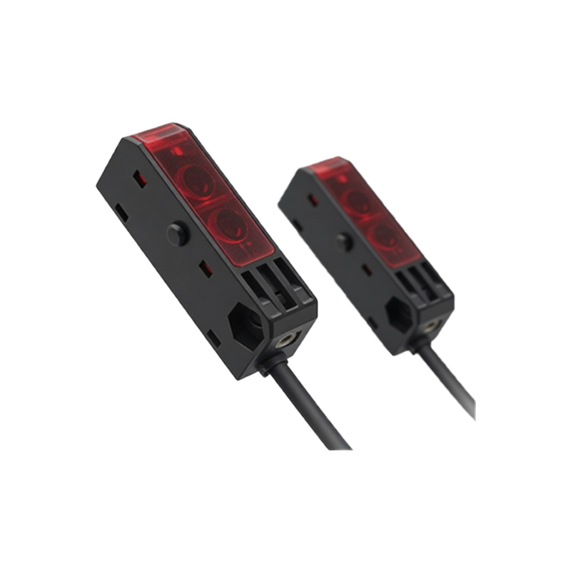
Modern variable frequency drives (VFDs) and servo drives often include dedicated digital input terminals for external control signals. A photoelectric sensor can be connected directly to one of these inputs to provide a run permissive, a positioning home signal, or a speed change trigger. For example, a sensor might detect when a product reaches a certain point on a machine, sending a signal to a servo drive to begin a precise positioning move. Similarly, a sensor could be wired to a VFD's "enable" input to allow a motor to run only when a safety guard is confirmed closed. This direct connection to the drive reduces wiring complexity and can decrease response time, as the signal does not need to be processed through a central PLC first. It is essential to consult the drive's manual to match voltage levels and understand the function of each input terminal.
Integration into Safety Circuits
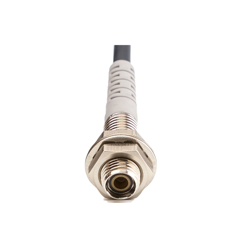
Safety-rated photoelectric sensors, such as safety light curtains or muting sensors, have a critical connection path. Their outputs are specifically designed to connect to the input channels of a Safety Relay or a Safety PLC. These devices are built to higher reliability standards with features like redundant circuits and self-checking. The connection is not merely for operational control but to create a reliable safety function, like halting a press brake when a hand is detected in the danger zone. The output from these safety sensors is typically a dual-channel signal that must be monitored by the safety device. If either channel indicates a break in the light curtain, the safety relay positively disconnects power from the hazardous machine actuators. This connection is governed by strict international standards like ISO 13849.
Linking to HMI and Data Acquisition Systems
Beyond direct machine control, photoelectric sensors are often connected to systems for monitoring and data collection. The sensor's output can be wired to a digital input on a Data Acquisition (DAQ) system or a remote I/O module that communicates via industrial networks like Ethernet/IP or Profinet. This allows the sensor's status to be displayed on a Human-Machine Interface (HMI) screen, providing operators with real-time visual feedback—such as a green indicator when a part is present. Furthermore, this data can be logged for production counting, Overall Equipment Effectiveness (OEE) calculations, or traceability records. In these scenarios, the connection serves an informational purpose rather than a direct control function, feeding data into supervisory systems for analysis and reporting.
Network-Based Connections via IO-Link
A significant advancement in sensor connectivity is IO-Link, a point-to-point serial communication protocol. An IO-Link capable photoelectric sensor connects to an IO-Link master module, not to a standard digital input. This single connection carries not just the simple on/off switch signal, but a wealth of digital data. Parameters like sensing range, response time, and operating temperature can be read from the sensor. More importantly, settings can be downloaded to the sensor remotely, enabling quick changeovers for different products. The IO-Link master then interfaces with the higher-level PLC via a traditional fieldbus or Ethernet. This connection method transforms the sensor from a simple switch into an intelligent device that provides diagnostic data, predicts maintenance needs, and simplifies system configuration.