Introduction to NPN Proximity Sensors
NPN proximity sensors are fundamental components in industrial automation, widely used for non-contact detection of metallic objects. These sensors operate on the principle of electromagnetic induction or capacitive sensing, generating a signal when a target enters their detection field. The "NPN" designation refers to the type of output transistor used within the sensor. In an NPN configuration, the output acts as a sinking switch. This means that when the sensor is activated, it connects the output signal line to the common negative (0V) rail, allowing current to flow into the sensor's output terminal. Understanding the correct wiring is crucial for ensuring reliable operation, safety, and integration with Programmable Logic Controllers (PLCs) and other control systems. A clear wiring diagram serves as the essential blueprint for this task.
Core Components and Electrical Characteristics
A typical three-wire NPN proximity sensor has three distinct terminals: Brown, Blue, and Black. The brown wire is universally designated for connecting to the positive supply voltage (typically +12V to +24V DC). The blue wire is always connected to the common negative or 0V DC supply. The black wire is the signal output line. The sensor's internal circuitry is powered continuously via the brown and blue wires. The key component is an NPN transistor whose collector is connected internally to the black wire, the emitter to the blue wire (common), and the base is controlled by the sensing element. When no target is present, the transistor is off, and the black wire is in a high-impedance state. Upon detection, the transistor switches on, effectively connecting the black output wire to the common blue wire.
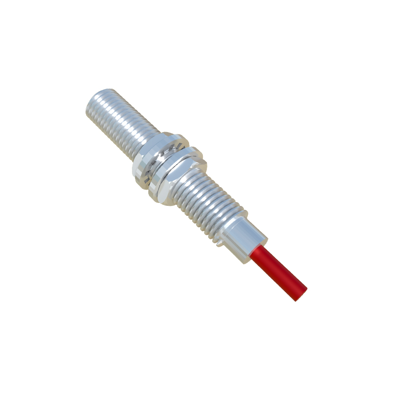
Standard NPN Wiring Diagram Configuration
The most common wiring setup involves connecting the sensor to a DC power supply and a load, such as a PLC input module. First, connect the blue wire to the negative terminal of the DC power supply. Second, connect the brown wire to the positive terminal of the same DC supply. The load (e.g., one terminal of a PLC digital input) is connected between the positive supply rail and the sensor's black output wire. The other terminal of the PLC input is connected to the common negative. When the sensor is inactive (no target), the NPN transistor is open, no current flows through the load, and the PLC input sees a high voltage (near +24V). When a target is detected, the NPN transistor saturates, sinking current. This pulls the black wire voltage down close to 0V, creating a current path from the positive supply, through the load, into the black wire, through the transistor, and out the blue wire to negative. This voltage drop to near 0V is read as an "ON" or "TRUE" signal by the PLC.
Connecting to a PLC Digital Input Module
Most modern PLCs have input cards designed to work with both NPN (sinking) and PNP (sourcing) sensors. For an NPN sensor, the PLC input card must be configured as a sourcing input. This means the internal circuitry of the PLC input provides a positive voltage (often through an internal pull-up resistor) to the input terminal. The wiring is as follows: Sensor Brown to +24V DC, Sensor Blue to 0V DC (the same 0V as the PLC power supply common). Sensor Black to the specific PLC input terminal. The PLC input circuit is internally connected to +24V. When the NPN sensor activates, it sinks this current to 0V, registering a logic low or "ON" state. It is critical to verify the PLC manual, as misconfiguring the input type or wiring can lead to non-operation or damage.
Considerations for Load Compatibility and Protection
The load connected to the NPN output must be compatible. Key specifications include the sensor's maximum output (sink) current, typically between 100mA and 200mA, and the residual voltage drop (often 1V or less) across the transistor when on. Exceeding the current rating can destroy the output transistor. For inductive loads like relays or solenoids, always use a protection diode (flyback diode) in parallel with the coil to suppress voltage spikes generated when the current is switched off. Furthermore, ensure the power supply voltage matches the sensor's rated voltage range. Using a regulated power supply minimizes electrical noise, which is vital in industrial environments to prevent false triggering. Always follow the manufacturer's datasheet for absolute ratings and connection diagrams.
Common Troubleshooting Steps Based on the Diagram
A correct wiring diagram is the first reference for troubleshooting. If the sensor fails to operate, systematically check these