Introduction to Photoelectric Sensor Technology
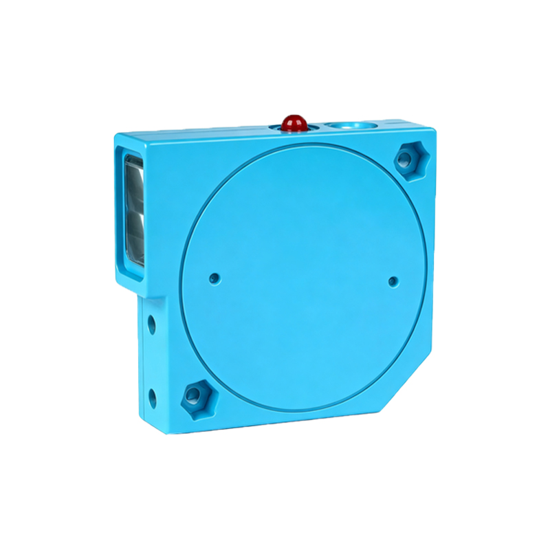
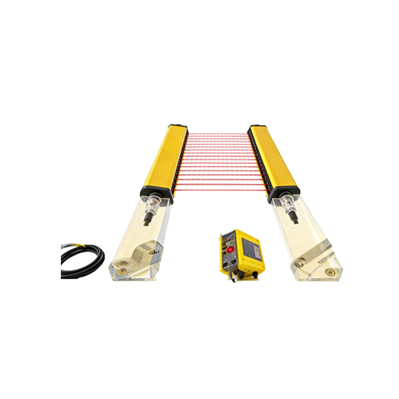
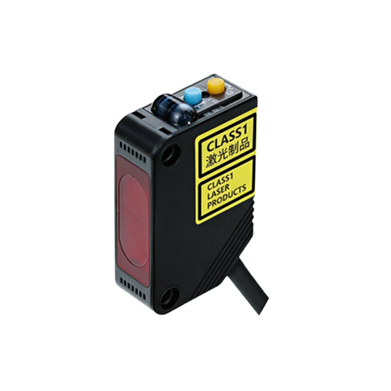
Photoelectric sensors are fundamental components in modern industrial automation, utilizing light beams to detect the presence, absence, or distance of objects. These sensors operate by emitting a light beam from a transmitter, which is then received by a photodetector. When an object interrupts or reflects this beam, the sensor's output state changes, generating a precise electrical signal. This principle forms the cornerstone for creating control pulses. The reliability, non-contact nature, and high-speed response of photoelectric sensors make them ideal for triggering events in complex machinery and production lines, where mechanical switches would fail due to wear or speed limitations.
Core Principles of Pulse Generation
A pulse generator, in this context, is an electronic circuit designed to produce a specific waveform—typically a square wave—with controlled timing parameters such as frequency, duty cycle, and amplitude. When controlled by a photoelectric sensor, the pulse generator's operation is initiated or modulated by the sensor's output signal. The sensor acts as the primary input or trigger. For instance, a retro-reflective sensor detecting a passing object on a conveyor belt can send a trigger signal to the pulse generator. The generator then outputs a defined pulse train, which can be used to control subsequent actions like activating a solenoid valve for a precise duration, driving a stepper motor for indexed movement, or marking a product.
System Architecture and Circuit Design
The integration of a photoelectric sensor with a pulse generator involves several key electronic stages. First, the sensor's output (often an open-collector NPN or PNP transistor output) requires conditioning. This may involve pull-up resistors, noise filtering capacitors, and voltage level shifting to ensure compatibility with the pulse generator's input circuitry. The heart of the pulse generator is typically a programmable timer IC, such as the classic 555 timer in monostable or astable mode, or a more sophisticated microcontroller like an Arduino or PLC-based timer function block. The sensor trigger configures the timer. In a monostable configuration, each sensor event produces a single output pulse of a fixed width. In an astable mode, the sensor might enable or disable a continuous pulse train. Design considerations must include power supply stability, isolation for high-noise industrial environments, and output driver stages capable of interfacing with relays, optocouplers, or motor drivers.
Key Applications in Industrial Automation
The photoelectric sensor-controlled pulse generator finds extensive use across various industries. In packaging machinery, it controls the cut-off length of materials; each sensor detection triggers a pulse that commands the cutter for a precise operation. In assembly lines, it enables precise counting and batch control. On bottling lines, a sensor detecting each bottle can trigger a pulse to activate a filling nozzle for an exact time period, ensuring consistent fill volume. In textile manufacturing, it controls the pattern length. Furthermore, in automated storage and retrieval systems (AS/RS), sensors detect pallet positions and generate pulses to control the travel and positioning of cranes with high accuracy, optimizing warehouse throughput and safety.
Advantages Over Alternative Control Methods
Utilizing a photoelectric sensor as the control element for pulse generation offers distinct benefits. Compared to mechanical limit switches, photoelectric sensors provide non-contact sensing, eliminating mechanical wear and allowing for much higher operational speeds and longer service life. They offer superior precision in detecting small or transparent objects. Compared to purely time-based pulse generators, a sensor-triggered system is event-driven, synchronizing operations directly with the physical process, which enhances accuracy and reduces waste. This setup also improves system flexibility; by simply adjusting the sensor's position or the pulse generator's timing parameters, the same hardware can be reconfigured for different tasks, facilitating quick changeovers in flexible manufacturing systems.
Implementation Best Practices and Troubleshooting
Successful implementation requires careful planning. Sensor selection is critical: choose the appropriate type (through-beam, retro-reflective, or diffuse) based on the detection range, object characteristics, and environmental conditions like dust or ambient light. The sensor must be mounted securely to prevent misalignment. Electrical wiring should follow EMI/RFI guidelines, using shielded cables and proper grounding to prevent false triggering from electrical noise. The pulse generator's timing parameters must be calibrated to match the mechanical response time of the actuators it controls. Common issues include false pulses due to sensor interference, which can be mitigated with adjustable sensitivity settings and time-delay functions. Another frequent problem is pulse width inconsistency, often traced back to power supply fluctuations or inadequate sensor response time for high-speed applications. Regular maintenance, including lens cleaning for the sensor and verification of timing settings, is essential for long-term reliability.