Introduction to Photoelectric Sensor Wiring
Photoelectric sensors are essential components in industrial automation, used for detecting the presence, absence, or position of objects without physical contact. Proper wiring is crucial for their reliable operation. This guide provides a comprehensive overview of wiring diagrams for various types of photoelectric sensors, including through-beam, retro-reflective, and diffuse reflective models. Understanding these diagrams ensures correct installation, reduces downtime, and enhances system safety. Each section details specific connections, common configurations, and troubleshooting tips to help engineers and technicians implement these sensors effectively in diverse applications, from packaging lines to material handling systems.
Basic Wiring Principles and Components
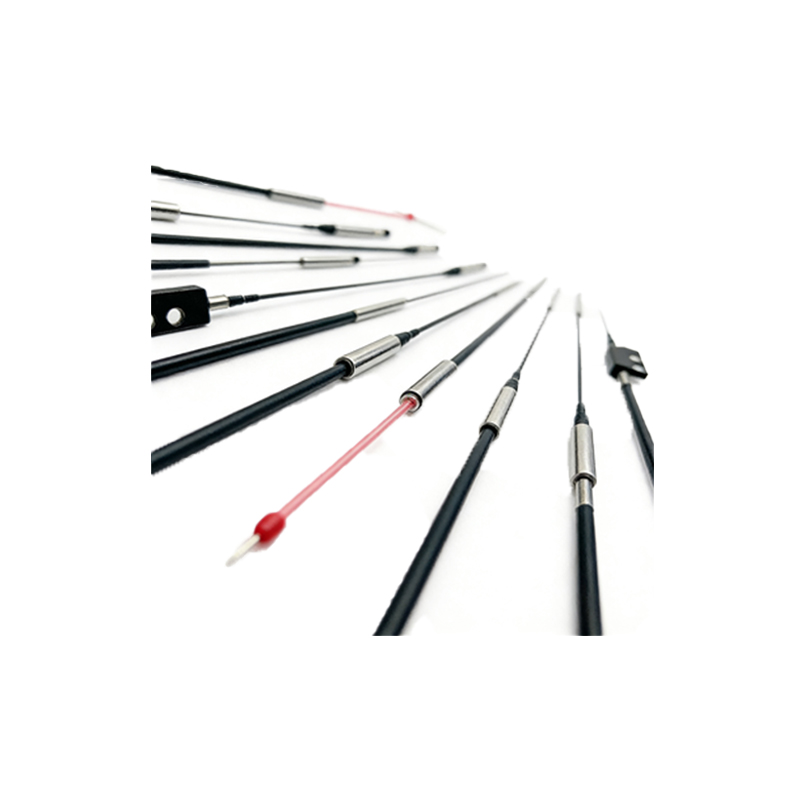
Before diving into specific diagrams, it's important to grasp the fundamental principles of photoelectric sensor wiring. Typically, these sensors consist of three main wires: power supply (often labeled V+ or brown), ground (0V or blue), and output (black or white). The power supply usually operates at 12-24V DC, though AC models exist. The output wire connects to a controller, such as a PLC, to signal detection. Additional wires may include timer functions or diagnostic indicators. Always refer to the manufacturer's datasheet for exact specifications, as colors and functions can vary. Ensure proper insulation and use shielded cables in noisy environments to prevent interference, which can cause false triggers or sensor malfunctions.
Through-Beam Sensor Wiring Diagram
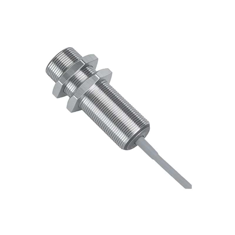
Through-beam sensors consist of separate emitter and receiver units. The emitter projects a light beam to the receiver; an object interrupting the beam triggers the output. For wiring, connect the emitter's positive terminal to the power supply (e.g., 24V DC) and the negative terminal to ground. The receiver's power connections are similar. The output wire from the receiver should link to the input module of a PLC or relay. A typical diagram shows: V+ to brown wire, 0V to blue wire, and output to black wire. Include a load resistor if required for current limiting. This setup is ideal for long-range detection but requires precise alignment, so secure mounting and periodic calibration are recommended.
Retro-Reflective Sensor Wiring Diagram
Retro-reflective sensors use a single unit that emits light and receives its reflection from a reflector. Wiring involves connecting the sensor's power pins to the supply and ground. The output pin interfaces with the control system. Some models feature a teach-in function for sensitivity adjustment, which may involve a separate wire or button. In diagrams, highlight the connection to a reflector and note that polarized filters can reduce false readings from shiny surfaces. For example, a common configuration is: brown wire to +V, blue wire to 0V, and black wire to PLC input. Test the sensor by placing an object in its path to verify the output signal changes state, indicating proper operation.
Diffuse Reflective Sensor Wiring Diagram
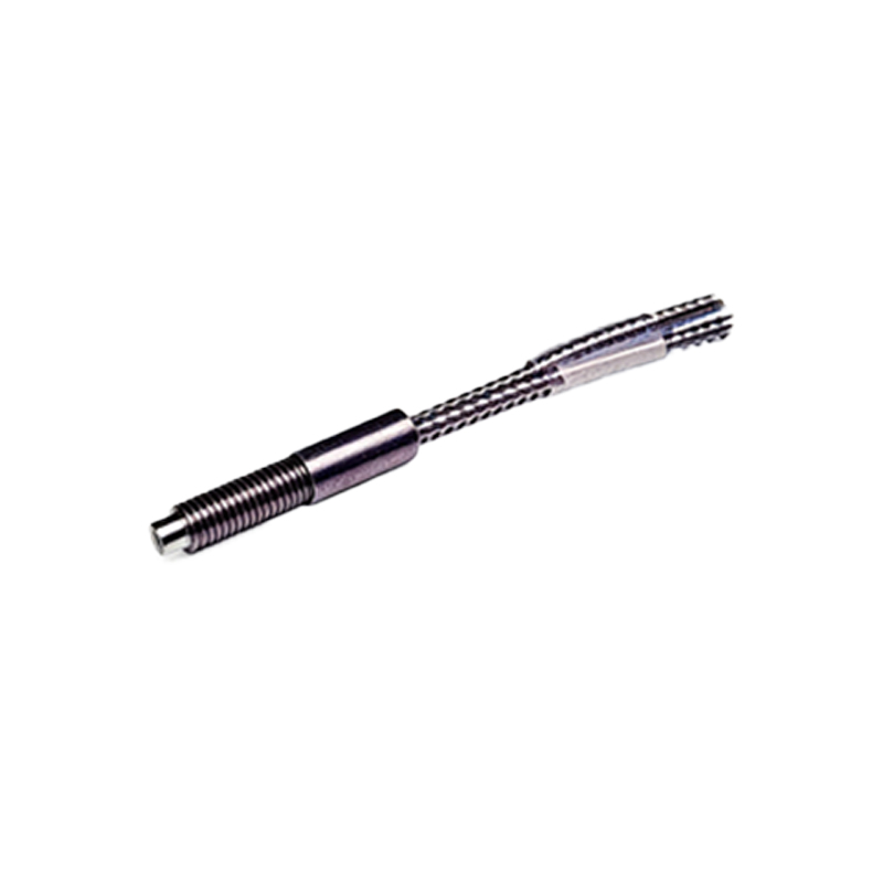
Diffuse reflective sensors detect objects by bouncing light off their surface. Wiring is straightforward: connect power and ground as with other types, and link the output to the controller. These sensors often have adjustable sensing ranges, so wiring might include additional terminals for setting parameters via external potentiometers. In diagrams, emphasize the target distance and material, as these affect performance. For instance, a typical setup shows brown to +24V, blue to GND, and black to a digital input. Use caution with dark or absorbent materials, which may require higher sensitivity settings. Regular maintenance, like lens cleaning, ensures consistent detection.
Wiring for NPN and PNP Output Types
Photoelectric sensors come with NPN (sinking) or PNP (sourcing) outputs, affecting how they connect to controllers. For NPN sensors, the output wire switches the ground side; wire it to the PLC's input, with the PLC's common connected to +V. For PNP sensors, the output switches the positive side; connect it to the PLC input, with the common linked to ground. Diagrams should clearly label these differences to prevent short circuits. For example, an NPN diagram might show: brown to +V, blue to 0V, black to PLC input, and PLC common to +V. Always match the sensor output type to the controller's requirements to ensure compatibility and avoid damage.
Advanced Wiring Configurations
For complex applications, photoelectric sensors may include features like analog outputs, IO-Link communication, or dual outputs. Wiring diagrams for analog outputs involve connecting a wire that provides a voltage or current proportional to distance, useful for positioning tasks. IO-Link sensors require a dedicated cable for data exchange with master devices, enabling parameter setting and diagnostics. Dual-output models might have separate wires for normally open and normally closed contacts. In diagrams, use clear labels for each function and include notes on configuration software if applicable. These setups enhance flexibility but require careful planning to integrate into existing networks.
Troubleshooting Common Wiring Issues
Even with correct diagrams, issues can arise. Common problems include no output signal, intermittent operation, or false triggers. Check connections for loose wires or incorrect polarity using a multimeter. Ensure the power supply voltage matches the sensor rating and that the load (e.g., PLC input) is within specifications. In noisy environments, verify shielding and grounding to reduce electromagnetic interference. Diagrams should include troubleshooting flowcharts: start by inspecting physical connections, then test power and output signals. If problems persist, consult the sensor manual for error codes or reset procedures. Regular audits of wiring integrity can prevent failures in critical systems.
Safety and Best Practices
Safety is paramount when wiring photoelectric sensors. Always disconnect power before making connections to avoid electric shock or equipment damage. Use appropriate wire gauges and connectors rated for the current and environment. Follow local electrical codes and standards, such as IEC or NEC. In diagrams, include safety symbols like earth ground for protective grounding. Implement redundancy for high-risk applications, such as using multiple sensors in series. Document all wiring changes and keep diagrams updated for future reference. Training personnel on proper installation techniques reduces errors and enhances overall system reliability, ensuring smooth operation in industrial settings.
Conclusion and Resources
Mastering photoelectric sensor wiring diagrams is key to leveraging their capabilities in automation. This guide covers essential types, from basic through-beam to advanced IO-Link models, with practical tips for installation and troubleshooting. Always prioritize manufacturer guidelines and safety protocols. For further learning, refer to industry resources like technical manuals, online tutorials, or training courses. By applying these principles, engineers can optimize sensor performance, minimize downtime, and contribute to efficient, safe industrial processes. Keep exploring new technologies, as sensor designs evolve with innovations in connectivity and smart manufacturing.