Understanding Proximity Sensor Fundamentals
Proximity sensors are indispensable components in modern industrial automation, detecting the presence or absence of an object without physical contact. They operate on various principles, primarily inductive, capacitive, and photoelectric. Inductive sensors detect metallic objects, capacitive sensors can detect both metallic and non-metallic materials, and photoelectric sensors use light beams. A clear understanding of the specific type installed—its sensing range, output type (PNP/NPN, NO/NC), and electrical specifications—is the critical first step in any troubleshooting process. Misidentification of the sensor type often leads to incorrect diagnostic paths and wasted time.
Common Symptoms of Sensor Malfunction
Recognizing failure patterns is key. The most frequent symptoms include intermittent detection, complete failure to detect any target, erratic or "chattering" output, and reduced sensing range. A sensor might trigger without a target present (false positive) or fail to trigger when a target is well within its specified range (false negative). Physical symptoms can also manifest, such as a damaged housing, cracked sensing face, or loose wiring connections. Documenting the exact symptom and the conditions under which it occurs (e.g., specific machine cycle, temperature) provides invaluable data for diagnosis.
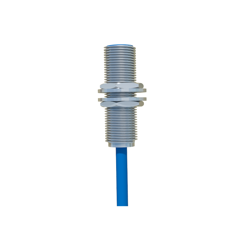
Systematic Electrical Verification Procedure
Begin troubleshooting with a methodical electrical check. First, confirm power supply voltage at the sensor terminals matches its rated specification (e.g., 10-30 VDC) using a multimeter. Voltage outside this range can cause malfunction or damage. Next, verify the output signal. For a DC sensor, monitor the voltage between the output wire and the negative supply. It should switch between a high state (close to supply voltage) and a low state (near 0V) when a target enters and leaves the sensing field. A stuck high or low output indicates an internal sensor fault. Always consult the sensor's datasheet for precise pinout and expected behavior.
Mechanical and Environmental Interference Checks
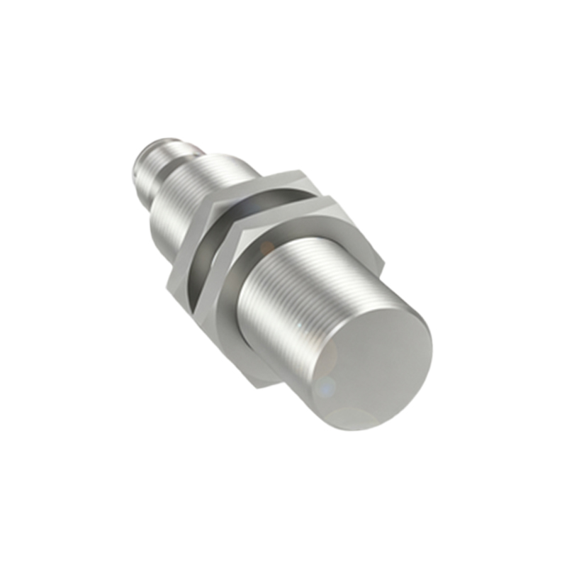
Many sensor issues stem from non-electrical causes. Ensure the target object is within the declared sensing distance and is of the correct material, size, and shape. For inductive sensors, different metals (steel, aluminum, copper) have different correction factors and reduce the effective range. Check for accumulation of debris, metal chips, or conductive dust on the sensing face, which can block detection or cause false triggering. Environmental factors like extreme temperature, humidity, oil/coolant splash, or strong electromagnetic interference from nearby motors or welders can severely impact performance. Verify the sensor's environmental ratings (IP, NEMA) are suitable for its installation location.
Installation and Alignment Pitfalls
Improper installation is a leading cause of premature failure. Ensure the sensor is securely mounted without excessive vibration. For side-sensing cylindrical sensors, maintain the recommended lateral and axial clearance from metal mounting surfaces and other sensors to prevent mutual interference. Photoelectric sensors require precise alignment; even a slight misalignment can break the light beam path. For reflective types, ensure the background is non-reflective and the target's surface properties (color, reflectivity) are compatible. Vibration can cause mounting hardware to loosen over time, gradually shifting alignment and causing intermittent faults.
Load and Wiring Configuration Errors
An incorrectly configured load can damage the sensor output. Verify that the connected load (e.g., PLC input, relay coil) does not exceed the sensor's maximum current rating. For 3-wire sensors, critically important is the correct wiring of the brown (positive), blue (negative/0V), and black (output) wires according to the sourcing (PNP) or sinking (NPN) configuration. Mixing PNP and NPN devices on the same common can cause short circuits. Check for damaged cables, insulation wear, loose terminals in junction boxes, and proper grounding. Shielded cables are often necessary in electrically noisy environments, and the shield must be grounded at only one end to prevent ground loops.
Advanced Diagnostics and Parameter Adjustment
Modern programmable sensors offer diagnostic LEDs and adjustable parameters. A status LED that remains off indicates a power issue; a solid LED may indicate a continuous output state or a fault mode. Flashing patterns are often coded to specific errors (refer to the manual). Some sensors feature sensitivity adjustments or timing functions (on-delay, off-delay). If sensitivity is set too high, it may detect background objects; if too low, it may miss the target. Timing functions, if misconfigured, can make the sensor appear unresponsive. Resetting to factory defaults can sometimes resolve software glitches.
Implementing a Preventive Maintenance Schedule
Reactive troubleshooting is less efficient than proactive