Introduction to Proximity Sensors
Proximity sensors are non-contact devices that detect the presence or absence of an object within a specified range. Widely used in industrial automation, robotics, and safety systems, these sensors operate based on various principles such as electromagnetic, capacitive, ultrasonic, or optical methods. Their ability to function without physical contact reduces wear and tear, ensuring longevity and reliability in harsh environments. This article provides a comprehensive visual guide to the internal and external structures of common proximity sensor types, aiding engineers and technicians in selection, installation, and troubleshooting. Understanding these diagrams is crucial for optimizing sensor performance in applications like object detection, position sensing, and limit switching.
Inductive Proximity Sensor Structure
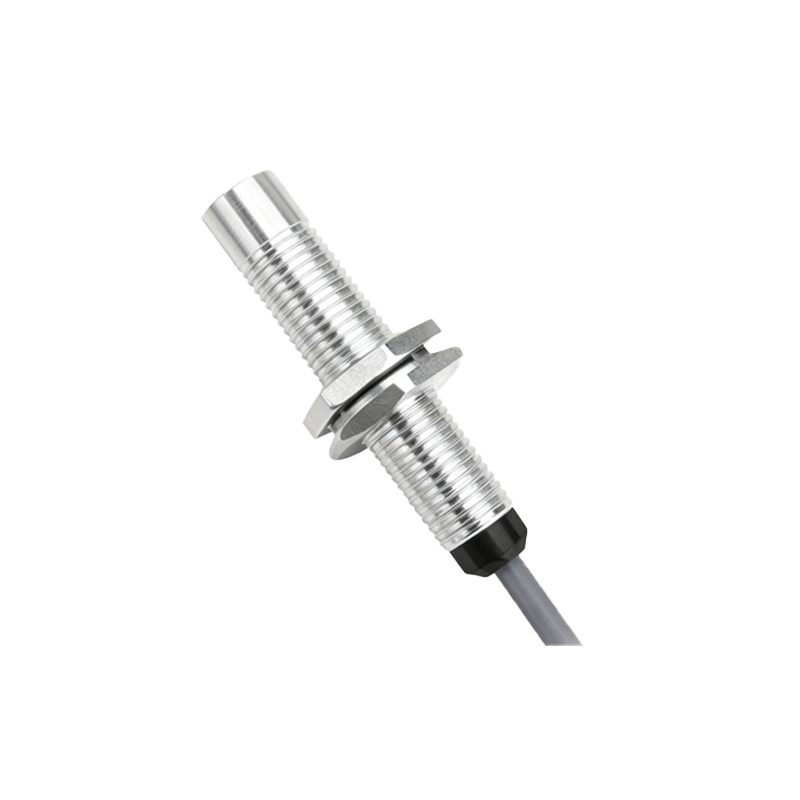
Inductive proximity sensors detect metallic objects using electromagnetic fields. The core structure includes an oscillator coil, ferrite core, signal conditioner, and output circuit. A diagram typically shows the coil generating a high-frequency electromagnetic field. When a metal object enters this field, eddy currents are induced, causing a change in oscillation amplitude. This change is detected by the sensing circuit, which triggers the output switch. Key components visible in diagrams are the sensing face (often made of plastic or ceramic), housing (usually metal or polymer for shielding), and wiring terminals. These sensors are ideal for detecting ferrous and non-ferrous metals, with ranges varying from a few millimeters to several centimeters.
Capacitive Proximity Sensor Diagram
Capacitive proximity sensors can detect both metallic and non-metallic objects by measuring changes in capacitance. Their structure comprises two conductive plates (electrodes) forming an open capacitor, an oscillator, and a detection circuit. In diagrams, one plate acts as the sensor face, while the other is connected to the ground. When an object approaches, it alters the dielectric constant, increasing capacitance and shifting the oscillation frequency. This triggers the output. Diagrams often highlight the sensing surface (typically plastic), shielding to reduce false triggers, and adjustment potentiometers for sensitivity control. These sensors are used for liquid level detection, material handling, and plastic object sensing, with detection ranges similar to inductive types.
Ultrasonic Proximity Sensor Layout
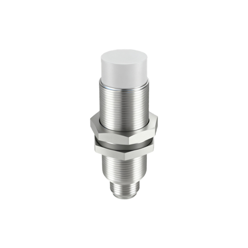
Ultrasonic proximity sensors use sound waves to detect objects. Structural diagrams display a transmitter (piezoelectric crystal) that emits high-frequency ultrasonic pulses and a receiver that captures reflected waves. The time delay between emission and reception calculates distance. Key parts include the transducer assembly, signal processor, and output module. Diagrams may show acoustic lenses for beam focusing and housing designed to minimize interference. These sensors work well for transparent, shiny, or irregularly shaped objects, with ranges extending up to several meters. They are common in automotive parking systems and conveyor belt monitoring.
Optical Proximity Sensor Components
Optical proximity sensors, including infrared and laser types, rely on light beams. Diagrams illustrate an emitter (LED or laser diode) and a receiver (phototransistor or photodiode). In through-beam sensors, these are separate units; in reflective types, they are housed together with a light reflector. Diffuse sensors combine emitter and receiver, detecting light reflected directly from objects. Structural details often include lenses for beam collimation, filters to block ambient light, and housing with alignment features. These sensors offer high precision for small object detection, color recognition, and clean environments, with ranges from millimeters to over tens of meters.
Magnetic Proximity Sensor Design
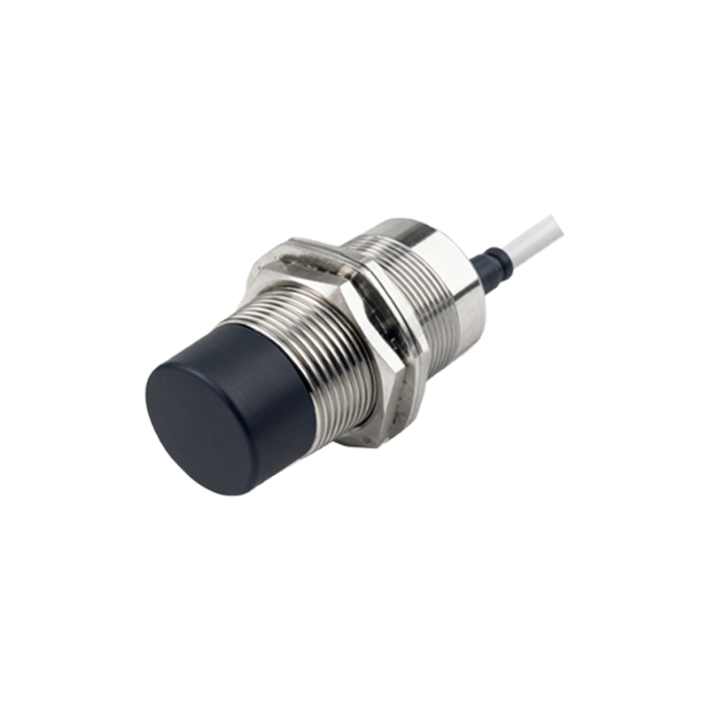
Magnetic proximity sensors detect permanent magnets using reed switches or Hall effect elements. Diagrams show a magnetically sensitive component (e.g., a reed switch with ferromagnetic contacts) sealed in a glass tube, connected to a circuit. When a magnet approaches, the contacts close or the Hall element generates a voltage, activating the output. Structures include protective housings (often plastic or stainless steel) and mounting brackets. These sensors are used in position sensing for cylinders, doors, and safety interlocks, offering long life and resistance to dirt and moisture.
Key Structural Features Across Types
Common structural elements in proximity sensor diagrams include housing materials (e.g., brass, stainless steel, or PBT plastic for durability), sensing faces (shaped to optimize field or beam projection), and electrical connections (like M8 or M12 connectors). Diagrams also highlight internal shielding to prevent electromagnetic interference, environmental seals (IP ratings for dust and water resistance), and LED indicators for status. Understanding these features helps in selecting sensors for specific conditions, such as high-temperature or corrosive environments.
Installation and Wiring Diagrams
Proper installation ensures sensor accuracy. Wiring diagrams typically depict power supply connections (DC or AC), output types (PNP