Introduction to Photoelectric Sensors in Automation
Photoelectric sensors are indispensable components in modern industrial automation, serving as the "eyes" of a manufacturing system. These devices detect the presence, absence, or distance of an object using a light transmitter and receiver. Their applications range from simple object detection on conveyor belts to complex positioning tasks in robotic cells. When integrated with a Programmable Logic Controller (PLC), photoelectric sensors form a critical link in the control loop, providing real-time input data that dictates machine behavior. Understanding the correct wiring methodology is paramount for ensuring system reliability, safety, and optimal performance. This guide delves into the technical specifics of connecting various types of photoelectric sensors to a PLC, adhering to standard industrial practices.
Core Components and Operating Principles
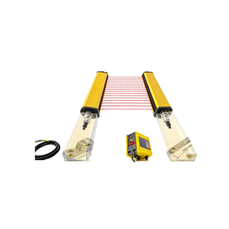
A typical photoelectric sensor consists of a light source (usually LED), a photoelectric receiver, and signal conditioning circuitry. The three primary operating modes are through-beam, retro-reflective, and diffuse reflective. Through-beam sensors have separate emitter and receiver units, offering the longest sensing range. Retro-reflective types use a single housing with both elements and a reflector. Diffuse sensors detect light reflected directly from the target object. Regardless of the type, the sensor's output is an electrical signal—either a digital ON/OFF switch or an analog value proportional to distance or intensity. This output must be correctly interfaced with the PLC's input module to be processed by the control program.
Understanding Sensor Output Types and PLC Compatibility
Before wiring, identifying the sensor's output type is crucial. The two most common configurations are NPN (sourcing) and PNP (sourcing). An NPN output switches the negative (common) line, while a PNP switches the positive line. This must match the sinking or sourcing input card of the PLC. Mismatching can lead to malfunction or damage. Many modern sensors offer selectable NPN/PNP outputs or push-pull circuits for universal compatibility. Additionally, sensors may provide a digital discrete signal (e.g., 24V DC for ON, 0V for OFF) or an analog signal (e.g., 0-10V, 4-20mA). The PLC must have a corresponding input module (digital input DI or analog input AI) to receive this signal. Always consult both the sensor datasheet and the PLC hardware manual for electrical specifications.
Step-by-Step Wiring Procedure for Digital Sensors
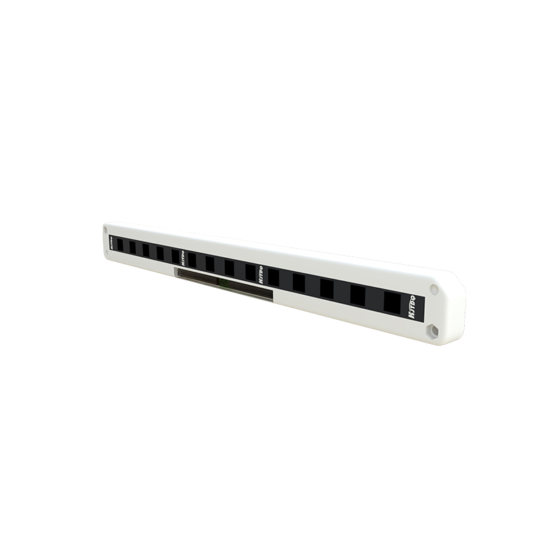
For a standard 3-wire DC digital photoelectric sensor (Brown: +V, Blue: 0V, Black: Output), the wiring to a PLC digital input module follows a systematic process. First, ensure the power to the PLC and sensor is OFF. Connect the sensor's brown wire to the DC positive supply terminal (e.g., +24V). Connect the blue wire to the DC common/negative terminal. The critical connection is the sensor's black output wire. For a PNP sensor, this wire connects to the designated terminal on the PLC's digital input card. The common terminal of that input group must then be connected to the DC negative (0V). For an NPN sensor, the black wire connects to the DC negative, and the PLC input is wired between the positive supply and the sensor's output, requiring careful configuration of the input card's common. Always use shielded cables for longer runs and ground the shield at one end to prevent electrical noise interference.
Wiring Analog and Special Function Sensors
Analog photoelectric sensors, which provide a continuous voltage or current signal proportional to the measured parameter, require connection to a PLC's analog input module. A 4-20mA current loop is industry-standard for its noise immunity. Typically, the sensor has power terminals (+V and COM) and two signal wires (I+ and I-). The +V and COM are connected to the power supply. The I+ wire goes to the positive terminal of the PLC analog input, and I- to the negative terminal, often forming a loop where the PLC module provides the loop power. Special function sensors, like those with IO-Link communication, use a 3-wire standard connection but enable bidirectional digital data exchange, transmitting detailed parameter and diagnostic data beyond a simple switch signal. Wiring remains simple, but configuration is done via software.
Safety Considerations and Best Practices
Safety is non-negotiable in industrial wiring. Always implement lock-out/tag-out procedures before working on electrical systems. Use the correct wire gauge as per current ratings and ensure all connections are tight. Fuse the sensor power supply line for protection against short circuits. Pay close attention to environmental factors: use conduit or appropriate cable jackets in areas with oil, coolant, or mechanical abrasion. For sensors in safety-critical functions (e.g., guarding), always use devices with safety ratings (e.g., SIL, PL) and wire them to dedicated safety PLC inputs. Proper labeling of all wires and terminals is essential for future troubleshooting and maintenance. Finally, after wiring, perform a thorough check for continuity and insulation resistance before powering up the system.
Troubleshooting Common Wiring Issues
Even with careful installation, issues can arise. A sensor not triggering the PLC input is a common problem. Begin by verifying power at the sensor using a multimeter. Check if the sensor's indicator LED activates when an object is present. If it does, the issue is likely in the wiring to the PLC. Verify the voltage between the sensor's output wire and the common terminal at the PLC input when the sensor is active; it should match the expected logic level (e.g., ~24V for a high PNP signal). Ensure no wiring mismatch between NPN/PNP and the PLC input type. Noise interference can cause erratic behavior; verify grounding and shield connections. For analog signals, check for signal scaling within the PLC programming software. Consulting wiring diagrams and using systematic diagnostic steps will resolve most connection faults efficiently.
Conclusion and System Integration
Correctly wiring a photoelectric sensor to a PLC is a fundamental skill for automation professionals. It establishes a reliable data link between the physical process and the digital control system. Once wired and verified, the sensor's input must be correctly addressed and logic programmed within the PLC software (e.g., ladder logic) to execute the desired control functions, such as starting a motor or incrementing a counter. Regular maintenance, including cleaning optical lenses and checking cable integrity, ensures long-term operational stability. By mastering these wiring principles and adhering to best practices, engineers and technicians can build robust, responsive, and safe automated systems that form the backbone of modern industrial productivity.