Introduction to Proximity Sensor Switches
Proximity sensor switches are fundamental components in modern industrial automation and control systems. These non-contact sensors detect the presence or absence of an object within their sensing field without any physical contact. This capability makes them exceptionally reliable, durable, and suitable for harsh environments where mechanical wear, contamination, or repeated impact would compromise traditional limit switches. They are widely used for position sensing, object counting, speed detection, and as safety interlocks. The core principle involves generating an electromagnetic field or a beam of light; when a target object disturbs this field, the sensor's internal circuitry triggers a solid-state switch. Understanding their internal structure is crucial for proper selection, installation, and troubleshooting in complex electrical panels and machinery.
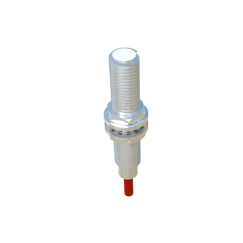
Core Structural Components and Housing
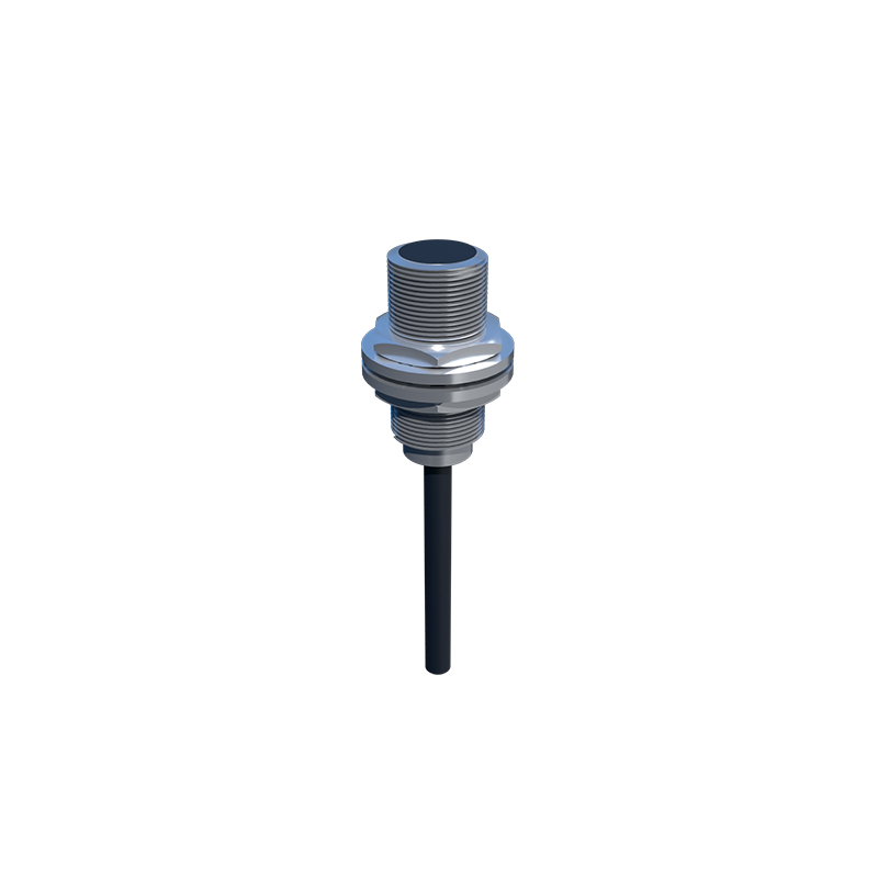
The external housing, typically made of metal (like brass or stainless steel) or robust plastic (PBT), provides mechanical protection and environmental sealing, often rated to IP67 or higher. This shell encases all internal elements and features a sensing face from which the field emanates. Key external parts include mounting threads or brackets, cable entries or connector types (e.g., M8, M12), and status indicator LEDs. Internally, the structure begins with the sensing element at the front. For inductive sensors, this is a coiled ferrite core that generates the high-frequency oscillating electromagnetic field. Capacitive sensors have conductive plates, while photoelectric types house the LED light source and phototransistor receiver. This front-end assembly is potted with epoxy resin to secure components against vibration and moisture.
The Oscillator and Detection Circuitry
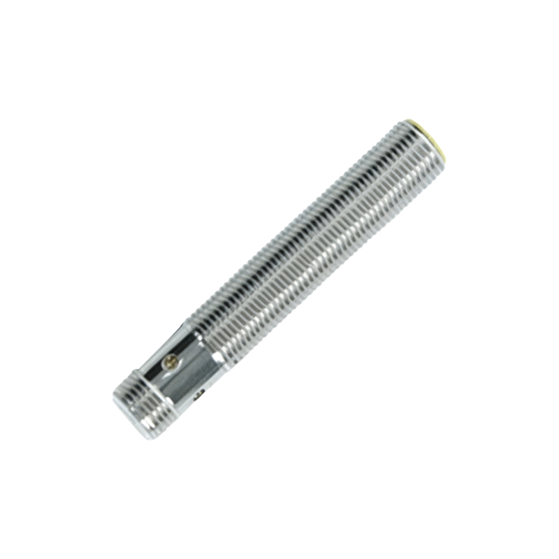
At the heart of an inductive proximity switch lies the oscillator circuit. This circuit, often built around a specialized IC, drives current through the coil at a high frequency (typically several hundred kHz), creating the alternating magnetic field at the sensor's active face. When a metallic target enters this field, eddy currents are induced on the target's surface. These eddy currents draw energy from the oscillator, causing a measurable decrease in the oscillation amplitude. The detection circuit, which includes a threshold comparator, continuously monitors this amplitude. Once the amplitude drop exceeds a pre-set threshold—corresponding to the sensor's specified sensing distance—the detection circuit sends a signal to the output stage. This entire process occurs with remarkable speed, enabling high switching frequencies.
Output Stage and Switching Mechanisms
The output stage is the component that interfaces with the programmable logic controller (PLC) or other control devices. Upon receiving the trigger signal from the detection circuit, it activates a solid-state switch. The two primary output types are NPN (sinking) and PNP (sourcing) transistor configurations. In an NPN sensor, the output transistor connects the load (e.g., a PLC input) to common negative (0V), effectively "sinking" current. In a PNP sensor, it connects the load to positive supply voltage, "sourcing" current. The output transistor is protected by a flyback diode for DC models or a snubber circuit for AC models to handle inductive load spikes. Some advanced sensors feature analog (4-20mA, 0-10V) or IO-Link digital outputs, which integrate signal conditioning and communication circuitry into this stage.
Power Supply Regulation and Protection
Integrated within the sensor body is a voltage regulation and protection circuit. This sub-assembly ensures stable operation despite fluctuations in the supply voltage (commonly 10-30V DC or 90-250V AC). It typically includes components like a voltage regulator IC, filtering capacitors, and resistors. Crucially, this section also provides protection against common electrical hazards: reverse polarity protection prevents damage if DC wires are connected incorrectly; short-circuit protection safeguards the output transistor if the load is accidentally shorted; and surge suppression (often using Metal Oxide Varistors) absorbs voltage transients from the power lines. This robust electrical design is what allows proximity sensors to operate reliably in electrically noisy industrial environments.
Internal Configuration and Adjustment Elements
While many standard proximity switches are non-adjustable, some variants include internal elements for configuration. These may include a potentiometer accessible through a small hole for adjusting sensitivity or hysteresis. Hysteresis is the difference between the switch-on and switch-off points, which prevents output chatter when a target is at the exact sensing limit. More sophisticated sensors might have DIP switches or teach-in buttons for setting operating modes (e.g., light/dark on for photoelectric), output function (normally open/closed), or timing functions (on-delay, off-delay). These components are mounted on a small printed circuit board (PCB) that connects the oscillator, detector, output, and power sections. The precise layout