Introduction to Photoelectric Sensors
Photoelectric sensors are vital components in modern industrial automation, used for detecting the presence, absence, or distance of objects without physical contact. They operate by emitting a light beam—typically infrared, visible red, or laser—and measuring the reflection or interruption of that beam. Common types include through-beam, retro-reflective, and diffuse reflective sensors, each suited for specific applications based on range, environmental conditions, and accuracy requirements. Understanding these basics is crucial before installation, as it ensures the right sensor is selected for tasks like object counting, positioning, or quality control in manufacturing lines. This tutorial will guide you through the installation process using a video format, emphasizing practical steps to avoid common pitfalls and optimize performance.
Pre-Installation Planning and Safety
Before starting the installation, thorough planning is essential. First, review the sensor's datasheet to confirm specifications such as sensing range, voltage requirements, output type (e.g., NPN or PNP), and environmental ratings like IP67 for dust and water resistance. Ensure the power supply matches the sensor's voltage (commonly 12-24V DC) to prevent damage. Next, inspect the installation site: check for ambient light interference, reflective surfaces, or obstructions that could affect the beam. Safety is paramount—always disconnect power to the machinery or control system to avoid electrical hazards. Wear appropriate personal protective equipment (PPE), such as gloves and safety glasses, and follow lockout-tagout procedures if working in an industrial setting. A well-planned setup reduces errors and enhances reliability.
Mounting and Alignment Techniques
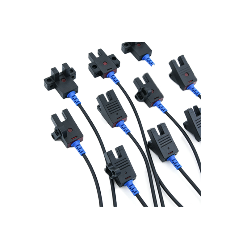
Proper mounting and alignment are critical for sensor accuracy. Begin by securing the sensor in its designated location using brackets or mounting hardware, ensuring it is stable and vibration-free. For through-beam sensors, align the emitter and receiver units precisely opposite each other, with the beam path clear of obstacles. Use alignment tools or the sensor's built-in indicators (like LED lights) to verify the beam is centered. For retro-reflective sensors, position the reflector so that the beam returns directly, avoiding angular misalignment. Diffuse sensors require careful adjustment of the sensing distance to account for object color and reflectivity—darker objects may need closer proximity. In the video tutorial, we demonstrate slow, incremental adjustments while monitoring the output signal to achieve optimal alignment. Avoid overtightening screws, as this can distort the housing and affect performance.
Wiring and Electrical Connections
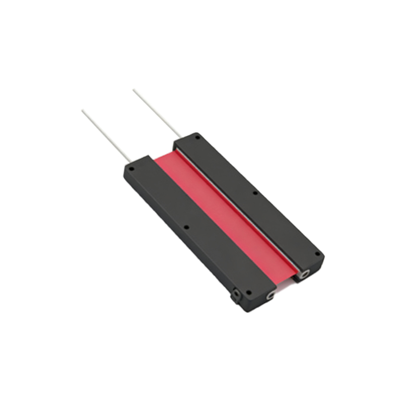
Correct wiring ensures the sensor integrates seamlessly with control systems. Refer to the wiring diagram provided by the manufacturer, typically showing connections for power, ground, and output wires. For DC sensors, connect the positive wire to the voltage supply and the negative wire to ground. Output wires link to programmable logic controllers (PLCs) or relays; for example, an NPN output sinks current to ground when activated, while a PNP sources current. Use shielded cables in electrically noisy environments to prevent signal interference, and route wires away from power lines or motors. Secure connections with terminal blocks or connectors to avoid loose contacts, which can cause intermittent failures. After wiring, perform a continuity test with a multimeter to check for short circuits or open lines before applying power. The video highlights common wiring mistakes, such as reversed polarity or incorrect output loading, and how to troubleshoot them.
Configuration and Testing Procedures
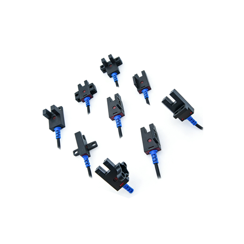
Once installed, configure the sensor settings based on your application. Many photoelectric sensors feature adjustable parameters like sensitivity, response time, or light/dark mode (choosing whether the output triggers on beam presence or interruption). Use potentiometers or digital interfaces to fine-tune these settings. For instance, increase sensitivity for detecting small or low-reflectivity objects, but avoid setting it too high to prevent false triggers from background noise. After configuration, conduct thorough testing: power on the system and observe the indicator LEDs. Pass an object through the sensing field to verify the output signal changes correctly. Measure response times with a timer or oscilloscope if high-speed detection is required. Document the settings and test results for future maintenance. The video tutorial includes real-time testing scenarios, showing how to calibrate for different materials and environmental conditions to ensure consistent operation.
Maintenance and Troubleshooting Tips
Regular maintenance prolongs sensor life and prevents downtime. Clean the lens periodically with a soft cloth to remove dust, oil, or debris that can scatter the light beam. Inspect mounting hardware for looseness due to vibration, and check cables for wear or damage. Common issues include false triggers from ambient light—solve this by using sensors with modulated light or installing shades. If the sensor fails to detect objects, recheck alignment and sensitivity settings. For electrical problems, use a multimeter to measure voltage at the terminals and ensure the output is switching properly. Log maintenance activities and any adjustments made. The video concludes with a troubleshooting segment, demonstrating how to diagnose and fix typical problems like intermittent signals or range reduction, emphasizing proactive checks to avoid system failures.